Weld profile monitoring using laser-based 3D imaging technology has recently advanced well enough to be a reliable tool for quality assurance on electro-resistive welding (ERW) and high-frequency (HF) welded tube and pipe mills. By applying 3D imaging techniques to a weld bead on formed ERW and HF welded tubes and pipes, a powerful monitoring technique can be implemented to provide ongoing weld profile monitoring on a tube mill.
While this technology has application on all types of tube and pipe welding, of particular interest is its application to weld profile monitoring of ERW and HF welded tubes. Properly monitoring the height and shape of the weld bead allows an inference of the quality of the weld, thereby enabling real-time detection of defects during production. But without the contour measurement technique offered by 3D imaging, it’s very difficult to measure common tube weld defects that change gradually, such as:
- Edge presentation (how well the two sides are presented to each other)
- Mismatch (typically, a linear height misalignment of the two sides as they come together)
- Size of the freeze line (the point of interface between the two faces of the tube which appears as a small concavity in the center of the weld).
3D imaging systems are based on triangulation measurements using a laser plane and a camera whose optical axis is offset to the axis of the laser plane (the “offset angle”). The resulting image shows a “cut-away” profile of the top section of the tube as if it was cut at the offset angle to the normal of the tube surface.
In ERW and HF welding, the bead size can be influenced by a number of factors during production, including the squeeze pressure exerted on the tube and the heat of the material as it passes through the welding zone. The improved measurement of bead height and shape made possible with laser-based 3D imaging allows for faster, more-accurate inferences about weld defects, so that production can stop until the problem is corrected.
In Figure 1, an image of a laser profile of a tube with a good weld is presented. The tube material outside of the weld bead shows a very clean indication of how the tube was formed, indicating a very clean edge presentation. The material on either side of the weld at its base is quite even, indicating a fairly low mismatch. Finally, in the center of the bead, a very small concavity exists which is still safe as it exists well above the base line of the weld. This concavity is the freeze Line, which particularly becomes a concern to weld operators when it goes below the surface of the tube, because once the weld bead has been removed through grinding or scarfing, there is a risk that a void of non-welded material could be present.
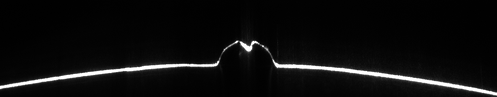
Figure 1: Weld with Proper Fusion and Minimal Freeze Line
Figure 2 demonstrates a void of non-welded material, where a deep freeze line has appeared due to insufficient heat of the tube as it passed through the weld zone. The freeze line extends low enough to possibly be below the tube surface once the weld bead has been ground or scarfed off. As a result, some exposed open weld could occur.
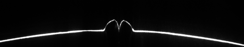
Figure 2: Poor Fusion Resulting in a Deep Freeze Line Caused by Insufficient Heat
Another type of defect that is clearly visible using 3D imaging is displayed in Figure 3, where low squeeze pressure has created a wide, sloped weld bead with low bead height. In such a weld bead, the integrity of the weld may be in question, as there may be insufficient fusion throughout the tube wall material because the sides have not been squeezed together sufficiently.
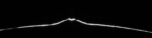
Figure 3: Weld with Proper Fusion but Low Squeeze Pressure
Often, these types of defects, as displayed in Figures 2 and 3, can occur in a slow, gradually changing manner. 3D imaging measurement systems make complete, absolute measurements of the contour of the weld in real time without comparing one measurement to a successive measurement. Therefore, those defects that gradually move out of tolerance are best detected using 3D imaging measurement systems, whereas other types of non-destructive testing systems will only detect something if there is a sudden anomaly in the tube structure or geometry.
The 3D imaging system can be placed shortly after the weld box, usually prior to scarfing, to automatically monitor the weld bead and forming immediately after the tube has been welded. By placing the measurement system right after the weld box, the weld profile can be instantaneously monitored to alert the operators for out-of-tolerance conditions as soon as they occur. That way, defects can be found sooner, avoiding the production of a long section of defective product before being detected by the line operators.
Overall, laser-based 3D imaging systems, such as the WI-2200/3000 Weld Inspection System from Xiris, offers an excellent measurement option for tube mill owners/operators who want additional, real-time monitoring of weld features. They can be used in a proactive manner, warning operators what is changing in their welding process so that they can perform corrective action before significant scrap occurs. As well, by measuring the outside contour of a weld, laser-based 3D imaging systems can operate on any type of material, regardless of its reflectance or magnetic properties, using a single head to perform the measurement.
Stay up to date by following us on social media or subscribe to our blog!
![]()
![]()
![]()
![]()