As a supplement to eddy current and ultrasonic testing, a laser weld monitoring system with 3D imaging allows for better monitoring of bead height and shape during ERW and HF tube and pipe welding. Operators gain valuable information about the weld profile to guide productivity-enhancing adjustments such as altering squeeze pressure or weld power.
How It Works
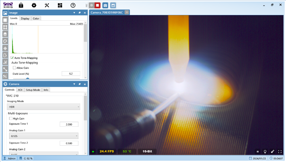
A laser weld monitoring systems projects a laser line across the weld bead, and a camera then looks at that line from an angle to extract a shape of the tube and bead surface that is displayed on the control screen. The operator sees a magnified round shape that is an accurate representation of the tube surface as reflected by the laser line. This line is the same as the top line that the operator would see when looking at a micrograph of a weld sample.
In addition to the displayed line, the laser system software can add a color reference line of a perfect circle to help the operator visually compare it to the displayed line. The software can also make measurements of left-to-right strip edge alignment (e.g., mismatch, bead height). And during production, the system can create a histogram to give operators a quick visual reference of how the last minute of production has been running.
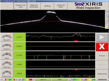
Histogram from Xiris Laser Weld Monitoring System
The usefulness of a particular laser weld monitoring system will largely be dependent on the capabilities of its software to provide operators with meaningful, quickly understandable information on the control display monitor. Operators don’t have time to decipher anything complex on the display.
A good laser weld monitoring system will use algorithms to turn huge data streams into visual indicators (e.g., sliders, light towers) on the screen that make it easy for operators to see at a glance how the process is going.
Alarm limits for each bead measurement can also be set. When any segment has variations that exceed the pre-set tolerance limits, an alarm will sound. These alarms don’t indicate specific problems, but they do let operators know that the process is no longer stable, and that section of tube can be spray-marked for further evaluation from quality-control staff.
The Setup
Laser weld monitoring systems can range in accuracy from 7 micron () per pixel and up. One size doesn’t fit all—systems must be tailored to each mill based on mill and product requirements.
Therefore, laser weld monitoring systems must be installed and aimed with care and diligence. Ideally, mill operators, quality control/quality assurance staff, and a production supervisor will work together to determine the tolerance levels to set. Once the correct threshold settings are determined, an operator is able to easily recall them for future reference—allowing the operator to run the system with increased efficiency, as long as it’s well maintained.
Conclusion
Laser remote weld monitoring systems—such as the Xiris WI2000p Weld Inspection System—can improve productivity and quality control of ERW and HF tube and pipe welding. However, proper installation, aiming, tolerance adjustment, and maintenance are required to take full advantage of this technology.