In previous blogs, we have discussed how high dynamic range (HDR) SWIR thermal imaging helps solve issues in welding and metal additive manufacturing. In this article we’ll go through the benefits of using an HDR SWIR thermal camera for another industrial process called thermal spraying.
Thermal spraying is a general name for a group of coating processes that use heat and particle velocity to create adhesion with the substrate. Thermal spraying is widely used for wear-resistant applications, thermal barriers, anti-corrosion coatings, etc.
The schematic below (Figure 1) shows a particle velocity-temperature map for a few major thermal spraying processes. The particle temperature can reach from a few hundred degrees to over 3000 °C in plasma spray and up to around 2000 °C in high velocity oxygen fuel (HVOF) processes. The powder temperature can also vary widely within the jet.
The temperature distribution control is key in thermal spraying. The temperatures of the particles, substrate, and the deposition area are critical for the coating adhesion and density that define the overall coating quality.
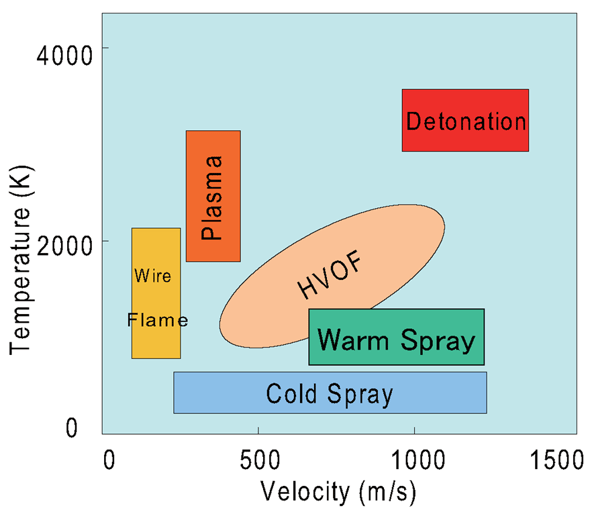 Figure 1. Velocity and temperature of the particles for several thermal spraying processes. Source: Wikipedia.org
High Velocity Oxygen Fuel (HVOF)
High velocity oxygen fuel (HVOF) thermal spray process is often used for wear-resistant coatings of tungsten carbide (WC), chromium carbide, and anti-corrosion stainless steel coating.
In this process, when the oxygen and gas fuel mixture is burned in a combustion chamber, it leaves the nozzle at supersonic speed (Figure 2). Powder is injected into this stream, so that it is accelerated to high velocities as well as heated to the temperatures of around 1000-2000 °C. The kinetic energy of powder creates an impact that helps form a hard, dense coating at relatively low temperatures. This is particularly important for temperature sensitive, high-strength steel applications like wear-resistant coating of aircraft landing gears.
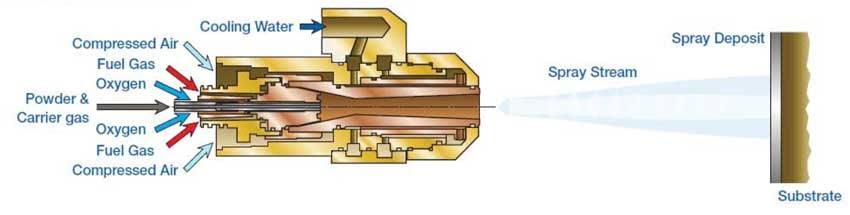 Figure 2. HVOF schematics. Source: mecpl.com
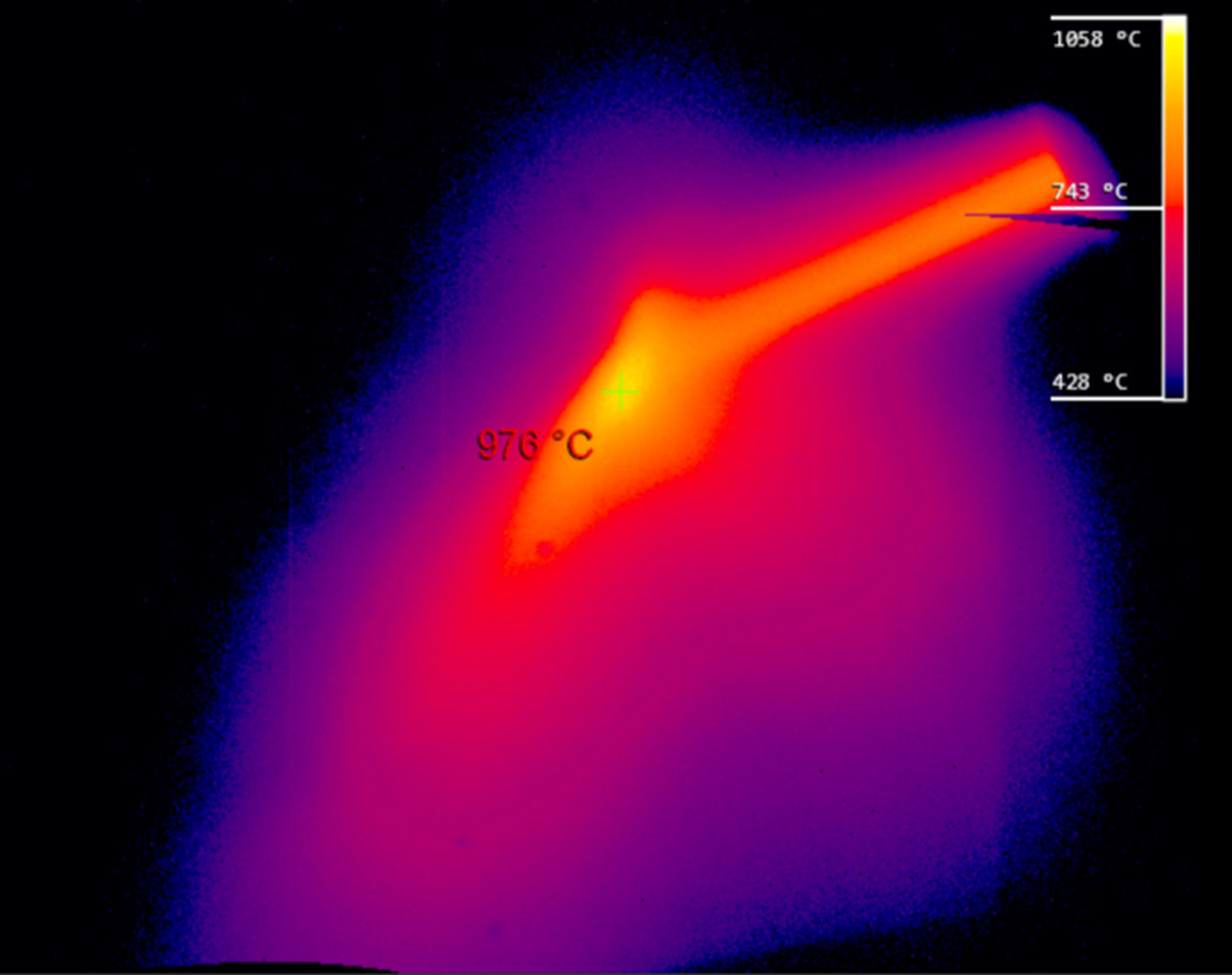 Figure 3. A thermal image of HVOF taken with a Xiris XIR-1800 Thermal Camera.
In HVOF, the temperatures of the particle stream, substrate and deposits are of great interest. The distribution of the particles in the stream and its uniformity is also important, as it defines local deposition density and can be affected by nozzle deterioration.
Thermal cameras are widely used in thermal spray, as temperature control is crucial for deposit quality. However, the major drawback of using conventional thermal cameras for thermal spraying applications is their low resolution. Low resolution imaging makes it challenging to spot smaller variations in the particle stream or the behaviour of the reflected particles after collision with the target.
Short exposure times and higher frame rates of HDR thermal cameras like the Xiris XIR-1800 help get a clearer image of high-speed processes compared to CMOS visible light cameras. For example, in HVOF, the torch typically moves around the substrate with a few cycles per second to create a uniform coating.
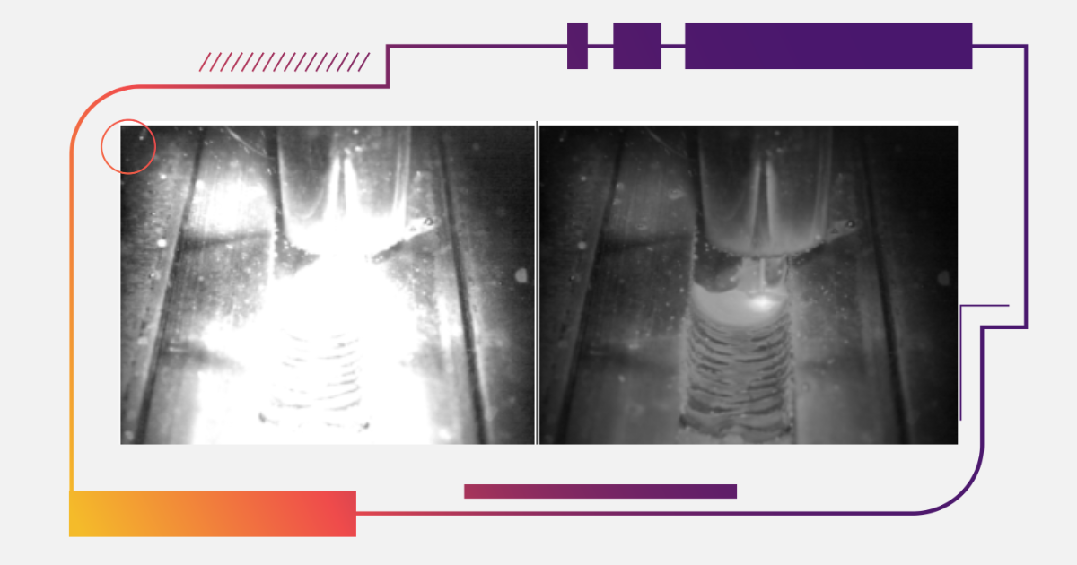
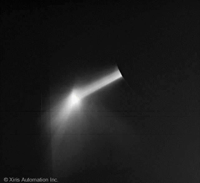 Figure 4. XIR-1800 SWIR image of HVOF. A split stream can be noticed at the top of the main particle stream. Also, faint supersonic shock diamonds may be noticed in the spray stream.
Aside from the temperature distributions, a high resolution camera such as the XIR-1800 allows operators the ability to see more details of their process. For example, in (Figure 4) above, a split component can be seen at the top portion the particle stream. This non-uniformity is likely a sign of nozzle deterioration and may affect the coating quality. In the example below (Figure 5), coating detachment can be noticed in a few areas at the bottom of the coupon due to imperfect process parameters, adhesion between the deposit and substrate was insufficient. As a result of poor attachment, these areas would overheat compared to the properly deposited coatings. Their higher temperature can be clearly seen in Figure 5.
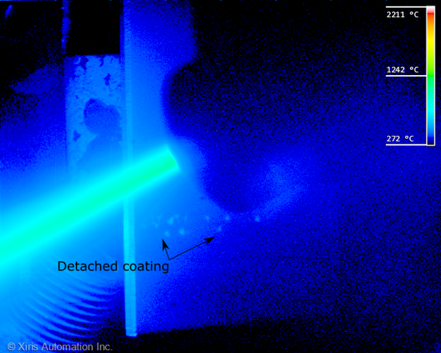 Figure 5. Improper process parameters of a coated layer led to its detachment. The detached area is visible in the thermal image as it is overheated during the process.
Plasma Spray
Plasma spraying is another widely used thermal spray process. It is characterized with much higher temperatures than HVOF and lower speed of the particles. Due to the high temperature of the plasma jet produced by an electric arc, it is often used to deposit ceramic., FAn example of this would be for zirconium thermal barrier coatings on jet engine parts, as the plasma plume is hot enough to melt or vaporize any known substance.
A schematic of the process is shown in Figure 6. The plasma jet is formed by an arc between the water-cooled cathode and anode and the plasma gas. The powder is inserted from a side as shown below or co-axially.
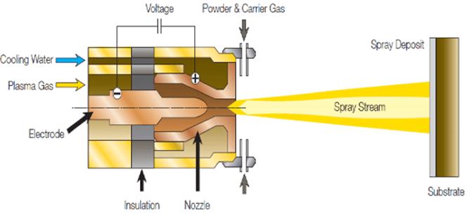 Figure 6. Plasma spray process schematic. Source: Bravo et al. (2020), Revista Mexicana de Ingeniería Química. 20. 229-239
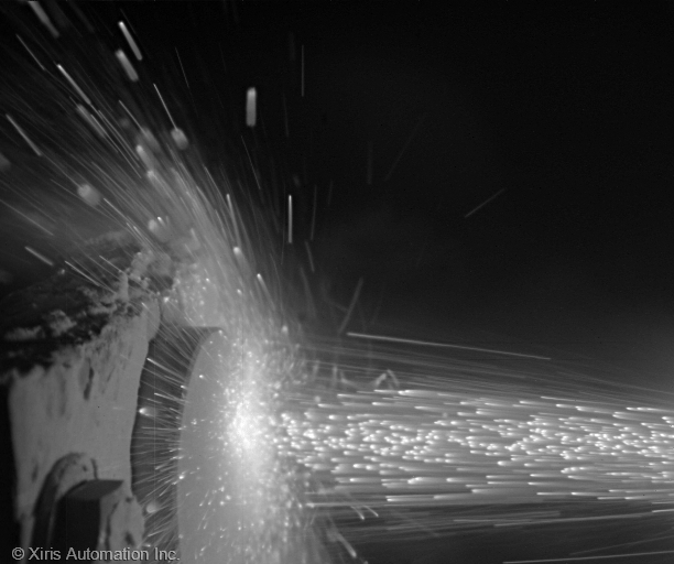
Figure 7. SWIR thermal image of plasma sprayed zirconium particles as they reach a coupon. In this example the round coupon was installed on a carousel spinning at 70 rpm.
Plasma sprayed particles have much lower velocity than those deposited by a HVOF process. The Plasma powder is also typically larger than that used in HVOF. Clear streaks of individual particles can be seen at the image above (Figure 7), taken with the XIR-1800 thermal camera with 5 ms exposure time.
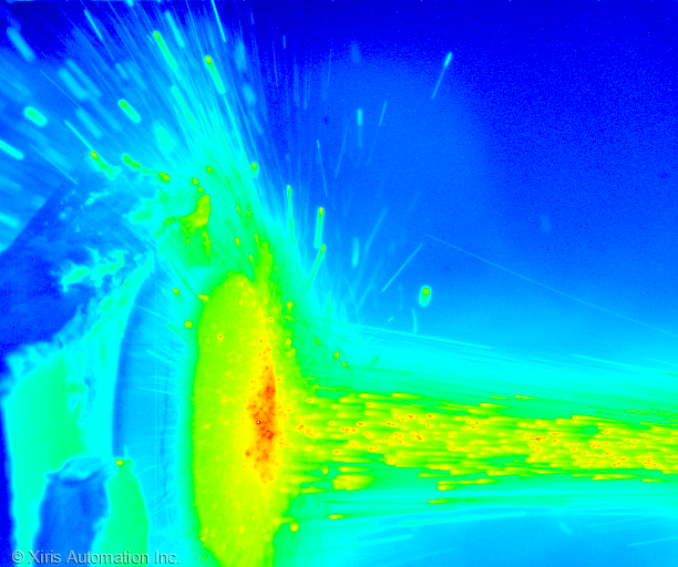 Figure 8. Thermal image of the plasma sprayed particles deposition onto a coupon.
To learn more about other thermal weld monitoring applications, visit our SWIR Thermal Imaging Guide. For more information on the XIR-1800 Thermal Camera, visit info.xiris.com/xir-1800 or contact one of our product experts.
Stay up to date by following us on social media or subscribe to our blog!
![]()
![]()
![]()
![]()