Welding Defects Guide: Types, Causes and Prevention
Welding defects are an inevitable challenge in welding processes, and understanding them is essential for ensuring the quality and safety of welded structures. This comprehensive guide provides an in-depth analysis of weld defects, detailing types, causes, prevention methods, and modern detection techniques such as non-destructive testing (NDT) methods like Xiris Weld Cameras. It equips you with the knowledge to optimize welding processes, minimize errors, and improve overall weld quality.
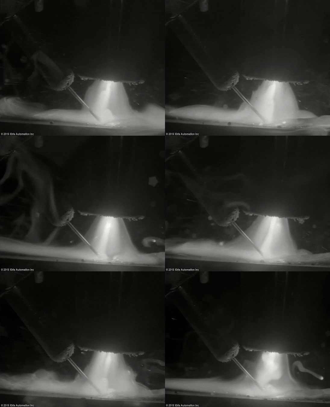
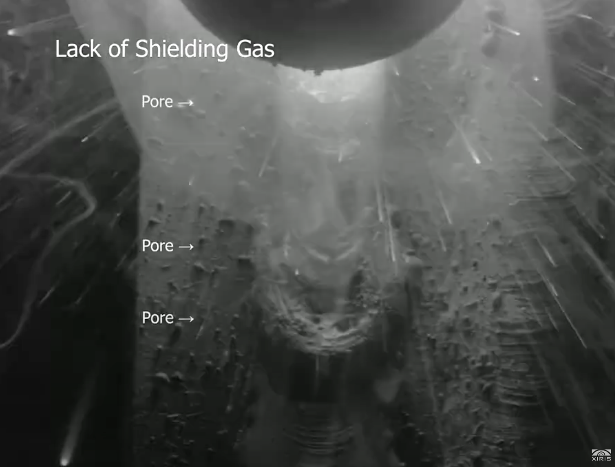
What Are Welding Defects?
Weld defects, or imperfections, are unwanted irregularities found in welds that can compromise the structural integrity and aesthetic quality of the welded piece. These defects, ranging from visible distortions to internal flaws, stem from various causes such as technique, material selection, and environmental conditions, and are often detected using non-destructive evaluation (NDE) methods or confirmed through destructive testing during failure analysis.
Understanding each defect and its potential solutions can greatly improve the quality of welding projects, making this knowledge essential for any welder or industry professional.
Categories of Welding Defects
Weld defects are typically classified into distinct categories, each reflecting specific aspects of the welding process that directly impact joint integrity and quality. This article will focus on three primary categories: dimensional imperfections, discontinuities, and surface defects, which arise as a result of welding parameters, application techniques, and process control.
Dimensional imperfections
Dimensional imperfections refer to issues in the shape or size of the weld bead, which can impact the weld’s structural integrity and durability. These defects often result from incorrect welding techniques or improper filler metal application, leading to weak joints or excessive material on the weld.
| Common Defects | Description |
|---|---|
| Under filled | Occurs when the weld bead lacks sufficient filler metal, resulting in weak joints. |
| Undercut | A groove at the weld toe that reduces the cross-sectional thickness of the base metal. |
| Overlap | Excess weld metal flows beyond the edge without bonding with the base metal. |
| Excess reinforcement | Too much filler metal on the weld bead, increasing the risk of cracking under stress. |
| Burn through | Results from excessive heat, causing the weld to penetrate through the base material. |
Discontinuities
Across different welding processes,
discontinuities are imperfections that interrupt the uniformity of the weld, creating areas of weakness that may compromise the welded structure. These defects can result from poor welding practices or environmental factors during the welding process.
| Common Defects | Description |
|---|---|
| Poor penetration | Occurs when the weld does not penetrate deeply into the base material, leading to weak bonds. |
| Lack of fusion | Failure of the weld metal to properly bond with the base metal, resulting in weak joints. |
| Cracks | Fractures that occur within or on the surface of the weld, potentially spreading and weakening the weld. |
| Slag inclusions | Entrapment of flux or slag particles within the weld metal, leading to weak spots and potential crack initiation. |
Surface Defects
Surface defects refer to imperfections that appear on the weld's surface, impacting both its appearance and, potentially, its structural integrity. These defects often arise from issues like contamination, rapid cooling, or inconsistent welding techniques. Surface defects can weaken the weld by creating stress concentration points or by allowing external elements to penetrate, but they can be identified through non-destructive visual inspection and advanced NDT methods.
| Common Defects | Description |
|---|---|
| Spatter | Small metal droplets that adhere to the surface around the weld, affecting appearance and quality. |
| Porosity | Gas bubbles trapped within the weld, creating weak spots and reducing strength. |
Metallurgical Defects
Imperfections related to the material properties and structural composition of the weld metal. These issues often arise due to improper heat treatment, rapid cooling, or variations in the composition of the weld and base metals. Metallurgical defects can weaken the weld by creating areas with different hardness, brittleness, or strength, leading to potential failure under stress. They may also affect the weld's resistance to corrosion or impact, depending on the environment and the welding process.
| Common Defects | Description |
|---|---|
| Segregation | Uneven distribution of alloying elements within the weld, causing inconsistent mechanical properties. |
| Microcracks | Small fissures within the weld metal that can lead to material failure under stress. |
10 Common Types of Weld Defects with Images and Videos
1. Underfill
Underfill occurs when there is insufficient weld metal in the joint, often due to low heat or inadequate filler material. This defect leads to a weld with a concave profile, where the joint lacks the necessary volume to bear structural loads.
The reduced weld volume directly impacts the joint's load distribution, making it vulnerable in applications with dynamic or concentrated stress points. Underfill welds often require rework in industrial settings, where precision and safety are paramount.
- Low Filler Metal Input: Insufficient filler metal during welding.
- Low Heat Input: Inadequate heat input creates a concave, undersized weld bead.
- Inappropriate Travel Speed: Improper travel speed fails to allow adequate material deposition.
- Increase filler metal deposition to create an adequately sized weld bead and avoid concave profiles.
- Adjust heat input to enable full coverage across the joint; maintain steady travel speed for uniformity.
- Apply multiple passes if needed to achieve the required thickness for load-bearing joints.
Underfill welding defect images


Video: Plasma - Robotic Assembly - Inconel (Turbine Fuel Injector) - Underfill Defect
This footage captures plasma arc welding (PAW) applied in a robotic setup for an Inconel turbine fuel injector. The process exhibits high thermal efficiency but presents an underfill defect. Such defects could impact fatigue resistance and necessitate parameter optimization for improved consistency.
Video: GMAW Defect – Butt Weld – Carbon Steel – Underfill
This footage captures gas metal arc welding (GMAW) applied for a butt weld joint with V-groove. Due to inadequate and increasing groove gap, the weld pool sinks and does not fill the groove sufficiently. As a result, an underfill defect occurs.
2. Undercut
Undercut is a defect seen as a groove along the weld toe where the base metal is eroded due to excess heat or high travel speed, leaving a depression that reduces the weld's effective cross-sectional area. This groove is often a product of disproportionate heat input, where the arc or torch melts the edge of the parent metal without fusing it back with additional filler.
The reduction in cross-sectional area acts as a stress concentrator, creating a vulnerable point susceptible to fatigue failure. In load-bearing structures, undercuts can significantly compromise the weld’s ability to withstand cyclic loading, leading to premature cracking.
- High Current: Excessive current that erodes the base metal edges.
- High Travel Speed: High travel speed limits fusion time, leaving exposed edges.
- Incorrect Electrode Angle: Inappropriate electrode angle directs heat towards edges without bonding.
- Lower the welding current to avoid excessive heat at the edges of the weld.
- Reduce travel speed to allow more bonding time; maintain a 5-15° electrode angle for even heat distribution.
- Use a weave technique to fill the edges effectively, especially on vertical welds.
Learn more about Undercut Defect
Monitoring Tube and Pipe Production to Find UNDERCUT Defects
Undercut welding defect images

Video: GMAW Defect – Fillet Weld – Carbon Steel – Undercut
This footage shows the formation of an undercut defect in gas metal arc welding (GMAW) of a fillet weld. Due to inadequately high wire feed rate and travel speed, the excessive arc pressure in the spray transfer mode leads to the formation of an undercut defect.
Video: GMAW Defect – Lap joint – Carbon Steel – Undercut
This footage shows the formation of an undercut defect in gas metal arc welding (GMAW) of a lap joint. Too high wire feed rate and travel speed lead to the formation of an undercut defect on the edge of the top plate.
3. Lack of penetration
Insufficient penetration is particularly problematic in applications with high-stress demands, as it compromises the weld’s ability to distribute load evenly. In load-bearing structures, this flaw necessitates rework to meet structural requirements.
Incomplete penetration leaves unfused areas within the joint that act as stress concentrators. These hidden discontinuities compromise the joint’s ability to handle tensile and bending loads and can lead to crack initiation under cyclic stress. In critical applications, this defect demands full rework to ensure structural reliability.
- Low Current Settings: Insufficient current that fails to reach the required joint depth.
- High Travel Speed: Excessive speed that reduces the arc’s ability to achieve full penetration.
- Improper Joint Fit-Up: Misaligned joint that limits the arc’s access to the entire joint surface.
- Increase current to reach the required depth within the joint, ensuring robust penetration.
- Lower travel speed for improved penetration; adjust electrode angle for full access.
- Ensure a proper joint fit-up to allow full arc exposure across the entire joint surface.
Lack of penetration welding defect images

4. Lack of fusion
Lack of fusion describes the incomplete bonding between layers of weld metal, often due to inadequate penetration or improper torch angles. This defect is especially common in multi-pass welding, where inter-pass cleaning is insufficient.
Lack of fusion weakens the weld interface, rendering it susceptible to delamination and cracking under stress. In critical applications, such as bridge construction or structural frameworks, this flaw necessitates strict inspection and rework protocols to ensure stability.
- Low Current Settings: Low current that limits the arc's penetration capability.
- Poor Joint Preparation: Inadequate joint preparation that hinders the interaction of the materials.
- Fast Travel Speed: Excessive speed that reduces the heat exposure time necessary for melting.
- Raise current settings to achieve deeper penetration and complete bonding along the joint.
- Prepare joint surfaces by cleaning thoroughly to remove contaminants that can obstruct fusion.
- Reduce travel speed to give the weld pool enough time to melt and fuse properly.
Learn more about Lack of Fusion
Using Video and Audio to Help Detect Welding Defects
Lack of fusion welding defect images


Video: GMAW Defect – Lap joint – Carbon Steel – Lack of Fusion
This video captures gas metal arc welding (GMAW) of mild steel in a fillet weld. The weld surface was contaminated with aluminum powder traces that caused the lack of fusion defect in the bottom plate.
5. Spatter
Spatter consists of molten metal droplets expelled from the weld pool due to high current settings or improper gas flow. These droplets solidify on the workpiece surface, requiring additional cleanup.
Beyond aesthetic concerns, spatter can affect component fit-up in assemblies and requires post-weld cleanup. While spatter does not directly weaken the weld, it can compromise the precision and surface finish required in high-quality manufacturing.
- Excessive Current: High current expels metal particles from the weld pool.
- Improper Polarity: Incorrect polarity affects arc stability.
- Insufficient Shielding Gas: Low gas flow results in scattered particles on the surface.
- Lower welding current to prevent excessive molten metal expulsion.
- Adjust polarity to ensure a stable arc; direct shielding gas to protect against airborne particles.
- Use anti-spatter spray as needed, especially on surrounding areas of the workpiece.
Learn more about Spatter Defect
8 Ways Weld Cameras Improve Productivity #2: Reduce Errors and Cut Costs
Poor Spatter welding defect images
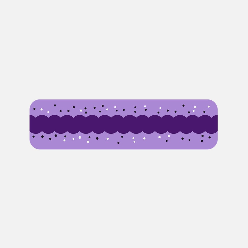
Video: GMAW Defect - Manual - Tee Joint - High Spatter (3 Coupon Welds)
This video captures a manual GMAW process on a Tee joint, highlighting spatter formation across three coupon welds. Despite stable arc behavior, moderate spatter is observed, likely due to shielding gas turbulence or voltage fluctuations. The bead remains consistent, ensuring sufficient fusion. Process optimization may reduce spatter without compromising penetration.
SMAW - Bead on Flat Steel Plate - Trailing - Lots of Spatter - Monochrome
This video showcases a SMAW bead-on-plate weld using a trailing technique. High spatter levels and irregular bead consistency suggest unstable arc conditions, possibly due to excessive amperage or inconsistent electrode angle. Arc intensity is relatively high, which may contribute to excess metal expulsion. Optimizing parameters could enhance bead uniformity.
6. Porosity
Porosity arises when gas becomes entrapped within the molten weld pool and solidifies as voids or bubbles, often due to contaminants, inadequate shielding gas, or residual moisture. During high-temperature welding, these gases escape unevenly, leaving pockets within the weld metal.
Porosity reduces the weld's density and strength, which is critical in pressurized environments. Applications in piping or pressurized vessels are particularly vulnerable, as porosity can lead to leaks and structural failures under operational stress.
- Contaminated Base Material: Presence of oxides, moisture, or oil that introduces gases into the weld pool.
- Inadequate Shielding Gas Flow: Insufficient shielding gas flow allows air and moisture to enter.
- Moisture in Filler Material: Moisture in the filler releases gas during welding, creating bubbles.
- Clean the base metal thoroughly to eliminate oils, rust, and dirt, which can introduce gas into the weld.
- Store filler materials in a dry area to avoid moisture absorption; preheat materials if necessary.
- Ensure proper shielding gas flow (15-20 CFH) and avoid drafts in the work area.
Porosity welding defect images

GMAW Defect - Stainless Steel - Robotic Automotive - Porosity
The robotic GMAW process on stainless steel exhibits significant porosity defects, likely due to shielding gas inconsistencies, oxidation, or entrapped contaminants. The instability in bead formation suggests inadequate process control, emphasizing the need for optimized welding parameters and environmental shielding conditions to mitigate gas entrapment.
GMAW Defect - Short Circuit - Butt Weld - Trailing Side View - Porosity
This video captures a GMAW short-circuit process on a butt weld, filmed from a trailing side view. The welding arc is active, but porosity defects are consistently visible along the bead. These defects were caused by surface contamination in the middle section of the weld.
7. Overlap
Overlap occurs when molten weld metal flows onto the surface of the parent material without bonding due to an inadequate arc angle or excessive filler deposition rate. This lack of fusion produces a superficial layer of metal, failing to create a cohesive bond.
Overlaps compromise the weld surface, reducing its corrosion resistance and creating potential points of weakness. This flaw is particularly detrimental in applications that require strict surface integrity, as it undermines the weld’s longevity and resistance to environmental degradation.
- High Welding Speed: Fast welding allows molten metal to flow onto the surface without bonding.
- Excessive Filler Metal: Too much filler metal is deposited without enough fusion control.
- Inadequate Heat Distribution: Insufficient heat distribution prevents bonding with the base metal.
- Maintain proper heat input to ensure the weld metal fuses with the base metal.
- Avoid excessive filler metal deposition; use consistent wire feed or rod addition.
- Keep a correct electrode or torch angle to guide the molten metal into the joint instead of onto the surface.
Poor Overlap welding defect images

8. Excess Reinforcement
Excess reinforcement occurs when an excessive amount of filler metal builds up along the weld bead, forming a pronounced convex profile. This is often the result of slow travel speeds or high filler deposition.
Although structurally less critical, excess reinforcement can create stress risers along the weld surface. It may also require grinding or other post-processing to achieve a uniform surface, particularly in applications requiring strict dimensional tolerances.
- Slow Travel Speed: Slow speed allows excess filler metal buildup.
- High Filler Metal Input: Too much filler material results in a convex bead.
- Improper Heat Control: Poor heat control leads to a bulky weld profile.
- Increase travel speed to avoid over-depositing filler metal and forming a convex profile.
- Control filler input for a balanced deposition; adjust heat input to achieve a flat bead.
- Plan to apply post-grind finishing only if necessary, as excess reinforcement may require it.
Excess Reinforcement welding defect images

9. Cracks
Cracks are fractures that appear as the weld cools, often due to rapid cooling, high residual stress, or incompatible material properties. Cracks may be longitudinal, transverse, or crater-type, depending on their orientation and cause.
Cracks represent a serious risk to structural integrity, serving as focal points for failure under cyclic or static loading. In industries such as aerospace, where component reliability is paramount, the presence of cracks necessitates comprehensive inspection and quality control.
- Rapid Cooling: Fast cooling induces internal stresses in the metal.
- Material Incompatibility: Materials with different thermal expansion rates cause tension.
- Residual Stresses: Residual stresses from improper welding techniques.
- Control the cooling rate to reduce residual stresses; preheat the material to slow cooling if needed.
- Use materials with compatible thermal expansion properties to minimize stress-related cracking.
- Employ a post-weld heat treatment when working with high-strength or brittle materials.
Cracks welding defect images

10. Burn through
Burn through happens when excessive heat penetrates entirely through the base metal, resulting in holes or thinning of the material. This defect is prevalent in thin sections where heat control is challenging.
Burn through drastically weakens the structural integrity of the joint, especially in precision applications such as pipeline welding. Such breaches in material continuity require rework to ensure that the joint meets industry standards.
- High Heat Input: Increase in current drives too much heat that burns through the base metal, especially in thin sections.
- Slow Travel Speed: Slow speed allows excessive heat, creating holes.
- Poor Edge Preparation: Inadequate preparation enables excessive heat penetration at the edge.
- Use lower heat input, especially for thinner materials, to prevent complete melting through the base.
- Increase travel speed to disperse heat over a larger area, preventing concentration.
- Ensure uniform edge preparation for even material thickness, which helps avoid burn-through spots.
Learn more about Burn through defect
Burn through welding defect images

Video: GMAW Defect - Carbon Steel Plate - Identified Burn Through Weld
This video demonstrates GMAW on a carbon steel plate. The high heat input led to a burn-through defect, visible as localized penetration irregularities. The weld bead lacks uniformity, indicating insufficient control of process parameters critical for preventing such defects.
Video: GMAW Defect - Carbon Steel Plate - Burn Through
In this video, the excessive heat input during gas metal arc welding (GMAW) of a lap joint lead to a burn through defect and subsequent collapse of the weld pool through the bottom plate.
11. Incomplete Fusion
Incomplete fusion occurs when the weld metal does not fully bond with the base metal or adjacent weld passes. It appears as an elongated gap along the weld, with sharp or rounded edges that indicate a lack of complete union.
Incomplete fusion weakens the weld by creating internal planes where stress can concentrate. Under cyclic or static loading, these planes can initiate cracks, leading to premature failure of the joint. Because of its impact on structural integrity, incomplete fusion is strictly limited by fabrication standards and typically requires full rework when detected.
- Improper electrode or torch angle: Limits heat transfer and prevents full bonding.
- Low heat input or excessive travel speed: Reduces penetration into the joint surfaces.
- Contaminated base metal: Oxides, oils, or dirt block proper fusion.
- Maintain correct electrode or torch angle to ensure heat is directed to the bonding surfaces.
- Adjust current and travel speed to provide adequate heat input for complete fusion.
- Clean the base metal thoroughly to remove all oxides, oil, and other contaminants.
Incomplete fusion defect images

12. Slag inclusion
Slag inclusion is a defect where nonmetallic slag particles remain trapped inside the weld metal or between passes. It appears as elongated lines or isolated pockets within the weld, often parallel to the weld axis, and can sometimes extend through the joint thickness.
Slag inclusions create discontinuities that concentrate stress and weaken the joint. They can also trigger localized corrosion in crevices where moisture collects. In critical structures, they reduce fatigue resistance and often require grinding and re‑welding to restore strength and meet inspection codes.
- Poor inter‑pass cleaning: Residual slag from previous weld passes remains trapped in the joint.
- Improper electrode manipulation or bead profile: Creates voids or pockets where slag can accumulate.
- Incorrect travel speed or current settings: Leads to uneven fusion and makes slag removal difficult.
- Clean and remove all slag between weld passes using chipping, wire brushing, or grinding.
- Maintain steady travel speed and proper current to ensure smooth bead formation and adequate fusion.
- Manipulate the electrode correctly to avoid pockets or undercuts that can trap slag.
Slag inclusion defect images

13. Arc Strikes
Arc strike is a defect that appears as small depressions, scars, or marks on the base metal where the electrode accidentally makes contact outside the weld joint. These spots melt briefly and cool rapidly, leaving localized blemishes or hardened areas on the surface of the base material.
Arc strikes can create small heat-affected zones that may harden and become brittle, especially in high-strength steels. These localized zones can act as stress concentrators, increasing the risk of crack initiation and propagation. In structural or pressure applications, arc strikes are considered unacceptable and often require grinding and inspection.
- Accidental electrode contact: Creates localized melting and surface marks.
- Poor tool or cable control: Allows unintended touching of the base metal.
- Sticking and breaking electrodes: Leaves small scars or depressions when detached.
- Keep electrodes, torches, and stingers clear of the base metal until positioned correctly.
- Use protective wraps or barriers on nearby surfaces to prevent accidental contact.
- Maintain steady hand control and proper grounding to avoid unintentional arc initiation.
Arc strikes defect images

14. Distortion
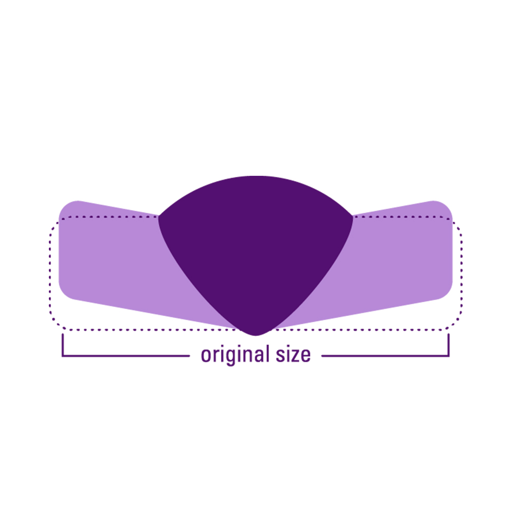
Weld distortion is the warping or permanent deformation of a welded part caused by the uneven expansion and contraction of the metal during heating and cooling. It often appears as bending, twisting, or misalignment of the workpiece after welding is completed.
Distortion can compromise dimensional accuracy, alignment, and structural reliability of welded assemblies. If uncorrected, it may lead to fit-up problems, additional rework, or reduced service life of the welded component.
- Uneven heating and cooling: Generates nonuniform expansion and shrinkage across the joint.
- Excess weld metal deposition: Increases shrinkage forces that pull the plates out of alignment.
- Poor joint design or unbalanced welding sequence: Fails to distribute stresses evenly.
- Limit weld size and avoid depositing more metal than necessary to reduce shrinkage.
- Use intermittent welding instead of continuous beads where design allows.
- Use fixtures, clamps, or preset assemblies to control and resist distortion forces.
Weld distortion defect images
15. Cold lap
Cold lap is a weld defect where molten metal flows over the surface of the base metal without fully fusing to it. It often appears as rounded edges, visible lines along the toes of the weld, or bulges where the weld metal overlaps the plate.
Cold lap creates weak points along the weld toes where cracks can initiate under stress. Because the metal has not fused properly, the joint’s load‑bearing capacity is reduced, and the defect can lead to premature failure if subjected to cyclic or dynamic loads.
- Low heat input: Prevents the molten metal from bonding to the base metal-
- Improper travel speed: Moving too slowly piles up metal without full fusion.
- Incorrect electrode angle or technique: Directs the molten pool away from the joint surfaces.
- Increase heat input to achieve proper fusion between filler and base metal.
- Maintain an even travel speed to allow the weld pool to wet and bond correctly.
- Hold the electrode or torch at the correct angle to ensure fusion along the weld toes.
Cold lap defect images


Weld Defect Detection with Xiris Automation Technology
Xiris’s welding cameras deliver real-time, high-resolution imaging that overcomes the limits of traditional inspection methods. Designed for continuous monitoring, they enable immediate defect detection and adjustments during welding, ensuring higher quality and improved productivity. Here's how:
- Real-Time, High-Definition Imaging: Unlike post-process inspections, Xiris cameras let operators monitor the weld pool, arc, and surrounding area live, catching issues like porosity or cracks instantly and adjusting on the spot.
- Detection of Subtle Inconsistencies: Advanced optics detect minor weld variations, such as penetration or alignment issues, crucial for precision applications to ensure high-quality results.
- Automated Data Collection for Improvement: Xiris systems record footage and data, enabling manufacturers to analyze trends, refine processes, and maintain compliance with traceable quality records.
- Non-Destructive, Continuous Monitoring: Xiris technology avoids production interruptions, offering real-time monitoring to reduce downtime and ensure consistent weld quality.
- Integrating Xiris cameras streamlines quality management, minimizes defects, and boosts productivity on the production floor.


