The Field of View you choose for your Weld Camera will play a critical role in getting the best-quality images for viewing the required details of your automated welding process.
But how large an FOV should you use for your camera? There are several factors to consider.
Camera Angle
The first question to ask is: What angle will we place the camera relative to the work pieces? The steeper the angle of the camera, the smaller the view of the weld head in the image and the larger the view of the weld bead and work piece. The shallower the angle, the larger the view of the weld head and the smaller the length of the weld bead and work piece in the image.
Depth of focus is an issue if you are looking at the weld using a camera that has been mounted at a low angle. The most important features in the weld should be kept in focus and be placed in the center of the FOV.
Camera Placement
When viewing the weld from the front, a general rule of thumb is to choose an FOV that is 4 x the bead width to be imaged. This FOV should provide you with most details of the weld in good image resolution.
If the camera is mounted from the side or behind the welding process, you need to ask yourself: What is the distance from the center of the weld head to the point in the weld bead where solidification occurs? It’s most useful to the operator if all these features are visible in one image.
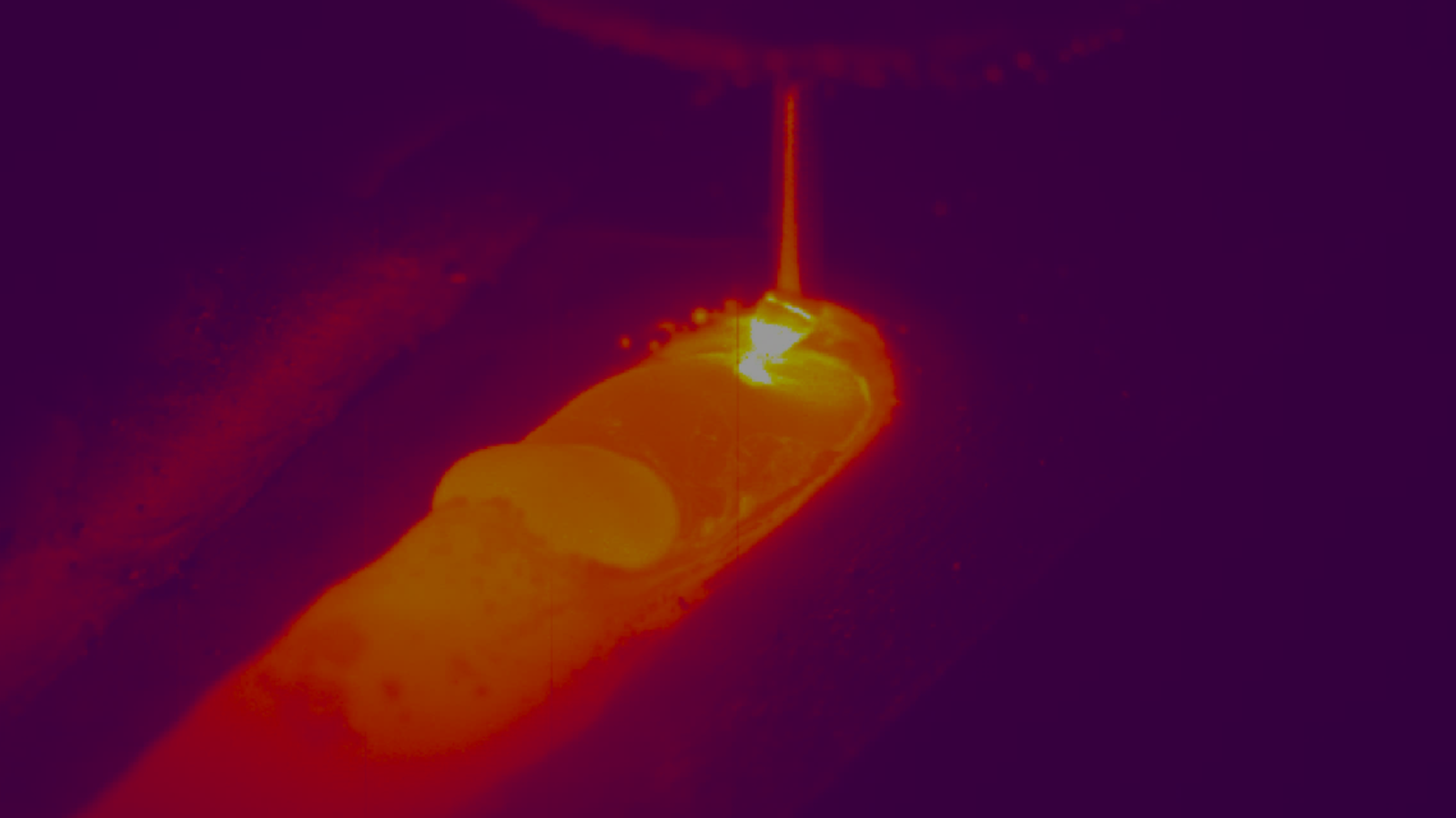
Ideally, you want to be able to see the weld bead as long as it is molten, the torch tip/arc, and some of the parent material (including the unwelded seam) all in a single view.
Type of Welding
For Narrow Groove welding, especially for the root pass where detail of the weld and the seam alignment are most critical, a suggested FOV could be 2 x the bead width. This would allow a closer view of the edges of the seam groove and weld pool to verify the best alignment between groove and weld head.
For subsequent passes after the root pass where weave welding occurs or where multi-pass welding is to take place, a larger FOV should be used to see the full movement of the weld head in a groove. In such cases, the FOV should be large enough to see the entire V groove.
In Cladding/Overlay applications, generally speaking, an FOV of 4 x the bead width should provide enough image size to see 1-2 previous passes of weldment, plus the current pass.
When filler material is used in a welding process, such as in GMAW (MIG), you need to select a FOV that will encompass the filler tip as well as all the other features of interest.
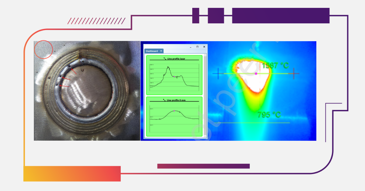
In Laser welding, special care must be made in selecting the appropriate FOV. Laser welding typically has very small welds and the Weld Camera may be limited as to how small an FOV can be used before optical distortions create a problem in the weld images.
Because Laser welding is typically a higher-speed application, it may be useful to choose a larger FOV (e.g., greater than 4 x the weld bead in this case) so as to see the entire molten pool after the weld head, as the tail of the weld pool may be longer relative to its width than what is found on MIG or TIG welding processes.
Conclusion
Selecting the right FOV is crucial in getting the highest-quality images for remote weld monitoring using a Weld Camera. Your decision should be based on your particular welding environment and operational demands.


.png)

