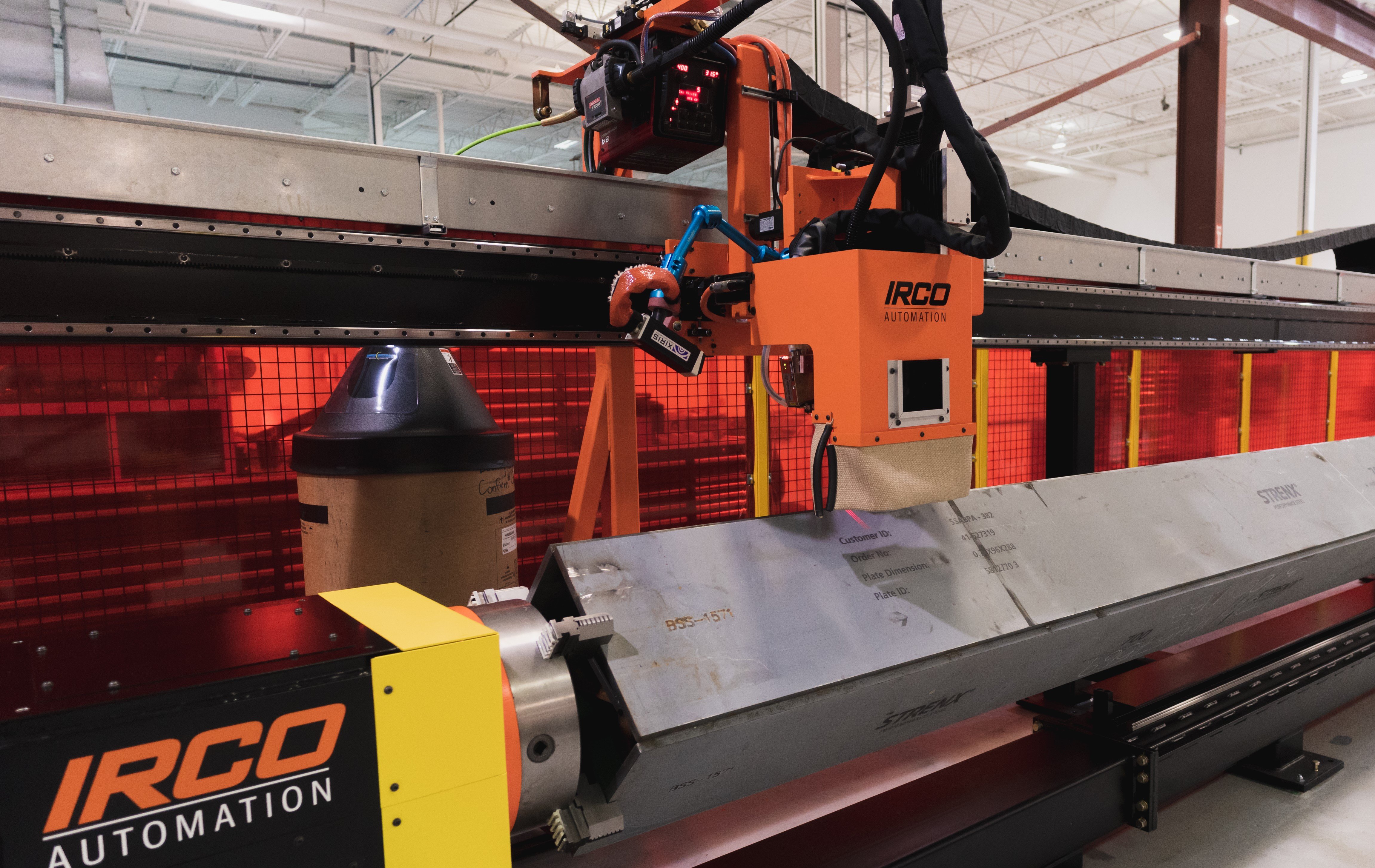
During the initial stages of automotive assembly, a car’s chassis is built up by welding together all its major sheet metal components, such as side walls, doors, door frames, roof joints, floor panels, the engine cavity and hood parts. The assembly process stage of welding all these components together is known as “body-in-white” and has been the source of much technology advancement in recent years.
One major technology advancement has been the introduction of laser welding processes to replace the traditional methods of fastening and joining the metal components. Laser welding offers numerous advantages over traditional techniques such as resistive spot welding but like any new technology, it requires more precise material preparation and careful process implementation.
Essential Advantages of using Laser Welding for Body in White
- Single-sided access to the point of welding, allowing for simpler chassis design in some situations.
- Better looking joints that are almost invisible are possible with some creative laser weld placement or by using laser brazing technology.
- The flanges required to hold together sheet metal components around apertures such as door openings can be smaller, leading to weight reduction and better automotive designs.
- Higher process speeds that can improve productivity, reduce cycle time, and reduce production floor space
However, there are disadvantages of the process….
- Tight Tolerances. The narrowly focused laser beam requires very precise seam preparation to ensure a successful result. Overlooking this in early automotive laser history resulted in many failures.
- Specific Repair Methods. Because laser welding is a relatively new joining method, repair techniques specifically designed for laser welding must be used when repairing laser welded joints.
The Solution
The solution to this problem is very precise seam preparation (with almost no gap) and precise clamping methods. But even with the best preparation, the seam can vary enough to cause problems with the weld process. With such a process, it is important to maintain very good alignment of the seam to the laser spot: because the laser beam is so small, a small movement of the seam out of alignment may jeopardize the quality of the alignment.
To solve this problem, a high dynamic range camera can be added to the laser process, either coaxially in the optics of the laser beam delivery system itself, or off axis. In either case, the camera can be positioned to see the laser keyhole, weld pool and weld seam. Because the high dynamic camera can see much more of the bright areas, including the weld pool and keyhole, as well as the darker areas such as the seam and background, it becomes much easier for operators to monitor the laser process to verify that it is in alignment.
Another “solution” involves the combination of laser welding and an open arc welding process (e.g. MIG or TIG) in a so-called hybrid process. For such a process, the open arc welding method delivers extra weld material that makes sure that the seam flanges are processed even without a precise seam; the laser permits deep penetration into the substrate, and the welding speed is significantly higher than if an open arc welding process was used on its own. Once again, the use of a High Dynamic Camera can help verify that all components of the weld environment are working correctly, in particular the alignment of the laser arc to the seam.

Figure 1: Camera Running Co-Axially to the Laser Beam Delivery System1
Conclusion
Laser processing continues to grow market share in a number of applications in body-in-white automotive manufacturing. However, as with any new process, it must be carefully implemented to take full advantage of the technology. To maximize the chances of success, a Weld Camera with a High Dynamic Range imaging capability should be used to provide operators with adequate weld visibility to monitor and control the laser to seam alignment before it moves out of control and causes defects in the welded seam.
_______________________________________________________________________
1. Adapted from: A. Ribolla et al. / Journal of Materials Processing Technology 164–165 (2005) 1120–1127


.png)

.png)
