Last month, we began a series on the Xiris Blog regarding defect detection on welded tubes with the Xiris Weld Inspection systems. We first discussed the scarf related measurements that can be used to detect issues in the process related to scarfing including scarf width, scarf depth and scarf defect.
As we mentioned, the WI systems can provide many measurements based on the differences between the actual laser profile line seen by the camera and the ideal mathematical profile. The diameter of the tube determines the length of the ideal profile line to be fit over the actual profile line. By knowing the position of the actual laser profile, the ideal profile, and the size of the pixels in the image, the WI-2200/3000 can then calculate various profile defects.
| Various Profile Defects: | |
| 1. Scarf Width 2. Scarf Depth 3. Scarf Defect 4. Deflection 5. Mismatch 6. Freeze Line |
7. Undercut 8. Left/Right Slope Angle 9. Bead Height 10. Bead Width 11. Bead Roll 12. Bead Ratio |
This month we are going to discuss two more of those measurements, which are mismatch and deflection.
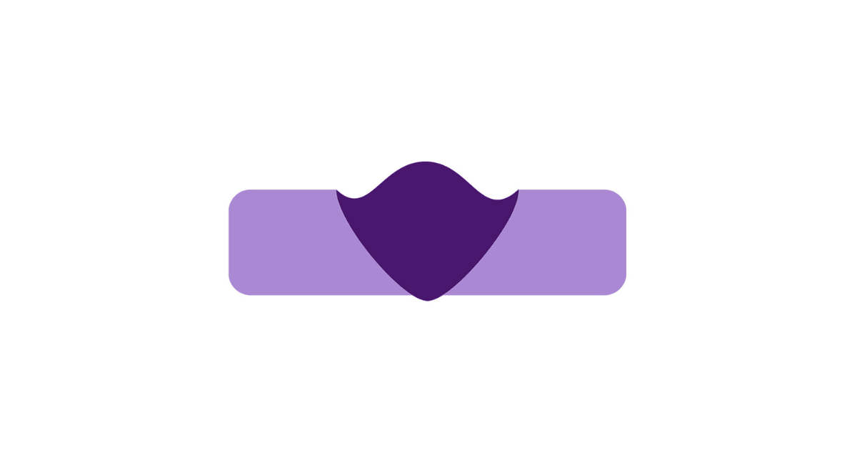
Mismatch:
The Mismatch defect looks for uneven joining of the two strip edges of the tube material at the weld point. Uneven joining could be a result of incorrect forming setup, edge break issues or twisting in the strip feed into the rollers. If Mismatch is present, this may result in significant thinning of one side of the tube wall after scarfing or grinding the weld area. Even without scarfing or grinding, the thickness of the welded tube wall in the bead area becomes smaller than the original tube wall thickness. This can lead to failure during corrugation, forming or bending of the tube. It is important to know the absolute value of the Mismatch, regardless of which side is higher than the other.
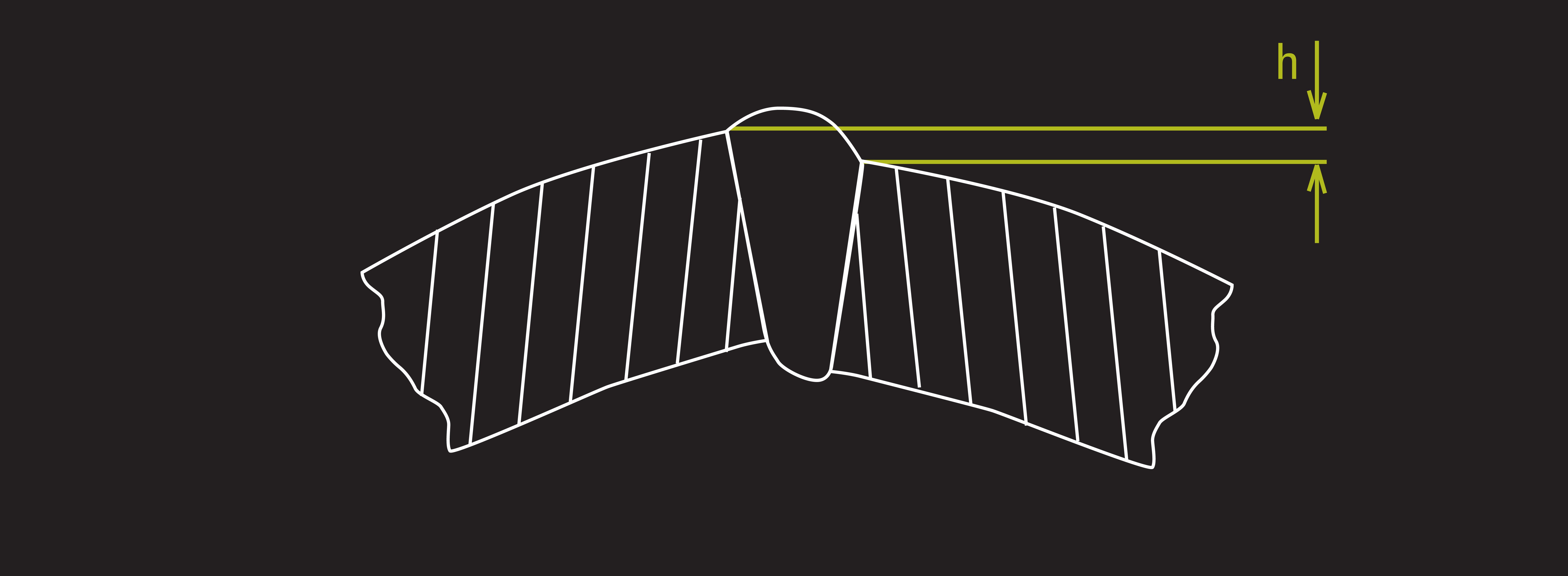
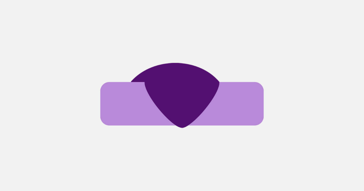
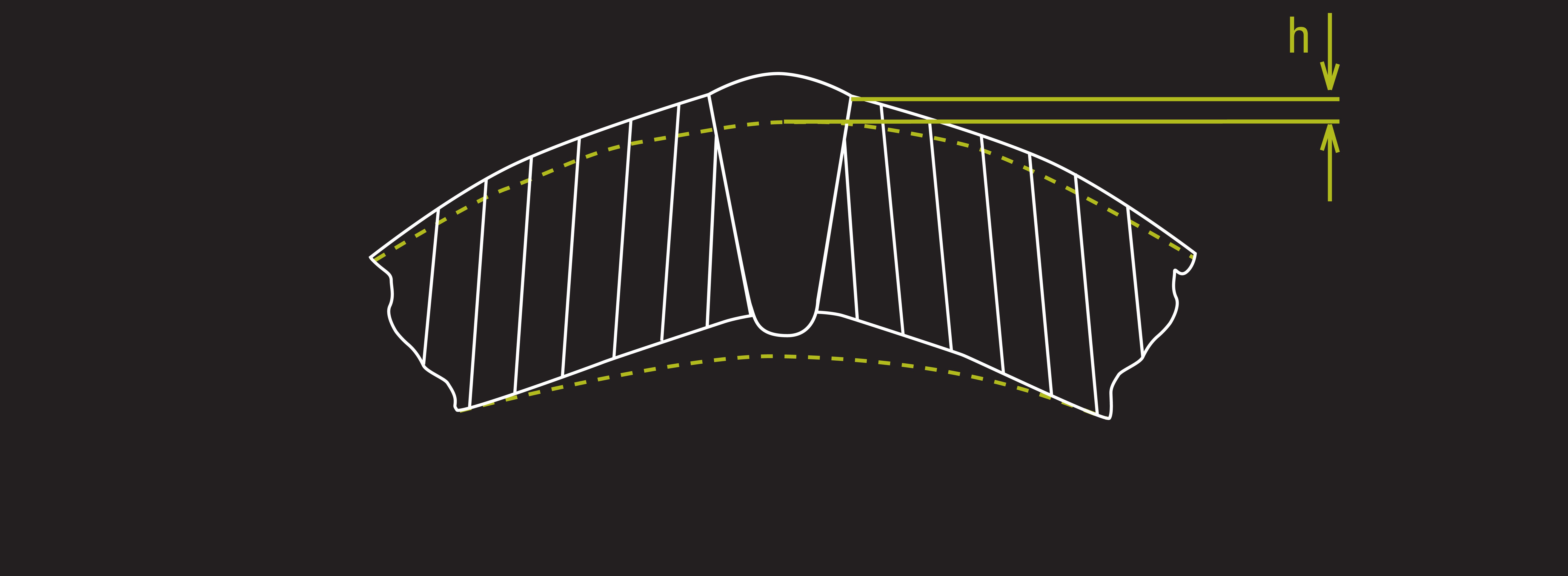
Deflection:
Deflection is measured as the distance from the ideal circle of the tube to the closest side of the tube within the bead area, measuring the distance between the flat sections outside of the bead and the ideal profile line. This measurement detects the overall deflection of the formed tube in the vicinity of the weld and usually represents the overall peaking of the tube walls at the weld point.
It is important to note that all other defect measurements provided by the WI systems are relative and are not affected by material deflection.
Using these measurements, operators can set thresholds so when a defect warning or failure limit is breached, an audio and/or light tower signal can be sent. The condition can also be sent to a defect marking system (paint or laser) that marks the area of the product where the error occurred for further inspection, repair, or removal.
Stay tuned as we continue to release more from this series or check out the previous blog on scarfing to learn more.
Stay up to date by following us on social media or subscribe to our blog!
![]()
![]()
![]()
![]()