Porosity is one of the most common and persistent defects in TIG welding. It appears as small pinholes on the weld surface or as hidden voids trapped beneath it. At first it may look like a minor cosmetic issue, but in reality porosity reduces strength, shortens fatigue life, and can create leak paths in components that must hold pressure or fluids. The challenge is that porosity doesn’t come from a single source. Contaminated base material, filler handling, moisture, shielding gas stability, and arc technique can all introduce gases into the molten pool. Once there, those gases may not escape before the metal solidifies.
Fortunately, the mechanisms are well understood, and so are the ways to prevent them.This article will clarify what porosity is in TIG welding, why it matters, the different forms it takes, the main physical causes, and the strategies you can use to prevent it.
What Is Porosity in TIG Welding
Porosity in TIG welding is the presence of gas cavities that remain inside the weld metal after it solidifies. These cavities form when gases become trapped in the molten pool and cannot escape before cooling. The result is a weld that looks continuous on the outside but contains empty spaces that weaken its structure. Several sources can introduce gas into the pool. Oils, paint, rust, and oxides on the base material or filler can decompose into gases. Moisture adds hydrogen, which dissolves in the liquid metal and separates as it cools. Shielding problems, such as drafts or poor gas flow, allow air to mix with the arc. If these gases are not released in time, they stay locked in the weld.
Porosity can appear in different forms. It may show as pinholes or small pits on the surface, or it may hide beneath the bead as clusters or isolated voids. In every case, it is a volumetric defect: the solid metal you intended to deposit is partly replaced by empty space that cannot carry load or create a seal.
Why Porosity Matters in TIG Welds
Porosity changes more than the appearance of a TIG weld. Even a few voids can weaken joints, shorten service life, or allow leaks where a seal is required. Open pores also create small pockets where contaminants or moisture can collect, leading to corrosion or surface problems. To see why prevention is essential, it helps to look at three main effects: reduced strength and fatigue resistance, loss of pressure integrity, and greater susceptibility to corrosion.
Strength and Fatigue Resistance
Porosity reduces the effective area of solid metal and concentrates stress around each void. Under cyclic loading, those concentrated stresses become crack initiation points. Scattered pores are less damaging than clusters, but both shorten fatigue life. On thin TIG welds the remaining ligaments can be very small, so cracks can form and grow much sooner than expected.
Leak Tightness and Pressure Integrity
When welds need to be airtight or liquid-tight, even a single pore can act as a channel. Several aligned pores can create the same effect, often leading to failures during pressure testing. This is especially critical in stainless and aluminum tubing where sealing is the main requirement. Stable shielding, clean preparation, and reliable back purging are essential to prevent leak-related porosity.
Corrosion and Surface Integrity Risks
Open pores create pockets that trap water, acids, or shop residues. On stainless steel this promotes localized corrosion and pitting. On aluminum, pores can hold oils or fluids that later stain or carbonize in service. Even subsurface pores can become visible if grinding or finishing exposes them. Preventing porosity ensures welds remain consistent in appearance and resistant to corrosion over time.
Types of Porosity Found in TIG Welds
Porosity in TIG welding doesn’t always look the same. The way gas gets trapped in the pool leaves distinct patterns, and each one points to different causes. Some pores are obvious on the surface, while others stay hidden until inspection. Sometimes they appear as scattered pinholes, other times they gather into dense clusters or form at the end of a weld. Grouping porosity into clear types makes troubleshooting faster because you can match what you see to the most likely source. In this section we’ll look at four common categories: surface pinholes, subsurface voids, cluster porosity, and crater porosity.
Surface Pinhole Porosity
Surface pinholes are small, round openings on the bead face. They can appear randomly or line up along the centerline if the gas coverage is uneven across the pool. Because they are visible, they are often the first hint that shielding, cleanliness, or environmental stability needs attention. The underlying mechanism is gas trying to escape, then freezing at the last moment as the skin solidifies. That can happen when airflow disturbs the argon plume, when arc length grows and lets air mix in, or when oils and moisture release gases late in solidification.
Subsurface Porosity
Subsurface porosity hides beneath a smooth bead. It forms when bubbles nucleate and grow within the pool but the surface stays closed. The joint can pass a quick visual only to show voids during sectioning, leak testing, or after a light face blend. Causes often include contamination that releases gas after the face has already skinned over, heavy heat input that slows gas escape, or inconsistent shielding that allows small amounts of air to mix with the pool without leaving obvious pinholes.
Cluster Porosity
Cluster porosity packs many small voids into a local zone. It tends to point at a single cause acting over a short distance. A draft that hits one section of a long seam, a contaminated patch on the base metal, or a segment of filler rod touched with oily gloves can all create a dense cluster. Clusters are more harmful than scattered pores because the remaining solid ligaments between voids carry higher stress and can crack earlier under load.
Crater Porosity
Crater porosity shows up at the end of a bead when the pool shrinks too fast without enough shielding or filler to keep the surface fed as it freezes. The shrinking pool concentrates gases in the last molten pocket, and a small pore forms right at the stop. This issue is common on thin material and around frequent starts and stops.
Causes of Porosity in TIG Welding
Porosity forms when gases become trapped in the weld pool and cannot escape before the metal solidifies. In TIG welding this occurs for a set of reasons, each tied to how materials, shielding, and process conditions interact with heat.
Contaminated Base Metal or Filler
When the base metal or filler carries oil, paint, rust, mill scale, or oxide films, those contaminants decompose under arc heat. The decomposition releases gases such as hydrogen and carbon monoxide, which dissolve into the liquid pool. As the weld cools, the solubility of these gases drops sharply, and they separate out as bubbles that may freeze inside the solidifying metal.
Shielding Gas Issues and Turbulence
Argon shielding protects the pool from atmospheric gases. If the flow is unstable, too low, too high, or disrupted, oxygen and nitrogen from the air mix into the molten weld. Once inside, they create bubbles or react with the metal to form compounds that leave voids. Turbulent gas flow also traps small volumes of air directly into the arc zone, leading to scattered porosity.
Moisture and Hydrogen Sources
Moisture on the joint, filler rods, or surrounding surfaces decomposes in the arc into hydrogen and oxygen. Hydrogen is highly soluble in molten metals like steel and aluminum. As the weld cools, hydrogen becomes less soluble, so it separates out of the solution and forms bubbles. This mechanism makes hydrogen one of the most common contributors to porosity across alloys.
Parameter Instability and Arc Technique
Heat input and pool geometry affect how easily gases can escape. High current with slow travel speed enlarges the molten pool, increasing the time it can absorb gases but not necessarily giving them time to rise out. A long arc length spreads the heat and stirs the pool surface, encouraging gas entrapment. Torch angles that expose the pool edge also let air mix in. Each of these conditions creates a pool that holds more gas and is less able to release it before freezing.
Lack of Back Purge on Stainless
On stainless steel, the root side of a joint left unshielded is exposed to oxygen and nitrogen. These gases dissolve into the molten metal at the backside of the weld. As the root solidifies, they become trapped as porosity along the interior surface. This mechanism explains why stainless welds without purging often show rough, porous roots even when the face appears clean.
How to Prevent Porosity in TIG Welding
Porosity can only be avoided when the welding environment is kept clean and stable, and when the weld pool is given the right conditions to release gases. At this stage the focus is not on why porosity happens but on the steps that stop it from forming in the first place. The following practices cover preparation, shielding, environment, parameter control, and modern monitoring tools.
Cleaning and Material Preparation
Any contamination on the joint or filler can release gas, so prevention starts with thorough cleaning. Remove oxides mechanically, wipe surfaces with a proper solvent, and allow them to dry fully before welding. Store filler rods in sealed containers, handle them with clean gloves, and wipe the section to be used. These habits eliminate the most common sources of porosity before the arc is struck.
Shielding Gas Quality and Coverage
Argon must cover the pool consistently from start to finish. Set flow rates appropriate to cup size, and use gas lenses when access is tight or joint geometry is complex. Keep hoses and fittings leak-free, and avoid turning flow so high that turbulence pulls air in. Maintain pre-flow to shield the start and post-flow to protect the crater until it solidifies.
Environmental and Joint Setup Controls
Shops are rarely still, and even light drafts can disturb shielding. Position work away from direct airflow or add barriers around sensitive welds. Hold joints with frequent tacks so geometry stays stable and arc length can remain steady. On stainless or titanium, maintain back purging until the root is cool enough to avoid oxygen pickup.
Parameter Stability and Heat Input Management
Stable parameters help the pool release any dissolved gas before freezing. Use current suited to material thickness, keep a short arc length, and maintain steady travel speed without long pauses. On thin material, pulsed TIG reduces average heat input while still achieving fusion, which keeps the pool compact and less prone to trapping bubbles.
Weld Cameras and Vision Systems
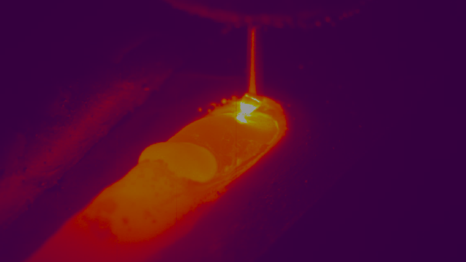
Visual monitoring adds a layer of prevention that goes beyond operator judgment. Weld cameras make bead shape, arc length, and shielding behavior visible in real time, as shown in Monitoring the Melt Pool from the Backside in Root Pass TIG Welding. When the bead widens suddenly or the heat-affected zone expands, adjustments can be made immediately instead of after porosity has formed. Vision-based seam tracking maintains consistent arc length and torch angle, while thermal imaging detects overheating early. Together these tools make porosity prevention more reliable and less dependent on trial and error.
Can You Correct Porosity After It Appears?
Repair is possible, though it isn’t the main strategy. Once porosity exists, the reliable fix is to remove the affected metal and re-weld under controlled conditions. Grinding or machining out the porous area clears the voids and gives you fresh material to fuse. Welding over pinholes without removal tends to trap more gas in place because the original voids become pockets that aren’t connected to the surface anymore. For surface pinholes, a small blend that reaches sound metal is usually enough. For clusters, removal may need to go deeper or wider to clear the entire region. On pressure or sanitary parts, a simple dye check after repair can confirm that no pores remain open to the surface. These steps work, yet they cost time and can change local geometry if repeated. Prevention remains the better investment. Clean materials, stable shielding, controlled parameters, and real-time vision or thermal monitoring keep porosity from forming and make repairs rare events instead of routine.
Troubleshooting Common Porosity Patterns
Even when welding conditions are well controlled, porosity can still appear. Specific appearances usually trace back to a small set of causes. By linking the pattern to its most likely source, you can focus corrections quickly rather than changing multiple variables at once.
Random Scattered Pinholes
These appear as isolated pores with no consistent location. They signal that shielding is breaking down intermittently. Corrections include checking for small gas leaks, steadying arc length, and blocking any drafts in the work area.
Start-Crater Pinholes
When pinholes are concentrated at the start of a bead, it means the weld pool was exposed before protection was stable. The fix is to increase gas pre-flow, position the torch so shielding covers the start zone, and ensure the surface is clean where ignition begins.
Mid-Bead Clusters
Clusters of pores appearing partway through a weld point to a local disturbance. Look for contaminated filler rod, sudden torch movement, or airflow crossing the joint. The corrective step is to clean or replace filler, maintain a consistent torch angle, and stabilize the work environment.
Aluminum-Only Chronic Pinholes
If pinholes keep appearing only on aluminum, the surface oxide and moisture are likely to blame. Corrections involve brushing oxide immediately before welding, using a dry dedicated filler, and adjusting AC balance or adding preheat to stabilize the pool.
Root-Side Porosity on Stainless
Porosity on the root face shows the purge was insufficient. Correct this by sealing the joint more effectively, flowing purge gas until air is fully displaced, and maintaining purge until the root cools below critical temperature.
Conclusion
Once porosity shows up, you can grind, blend, and re-weld, but each cycle consumes time, changes local geometry, and risks locking in new voids. A better endpoint is a process that makes porosity rare in the first place by preventing it. That means treating cleanliness as part of fit-up, not an afterthought, and treating shielding as a controlled environment rather than a flow number on a gauge. It also means shaping the molten pool with parameters you can hold steady, then verifying what the pool is actually doing with eyes that do not blink. This is where Xiris weld cameras and their clear, stable views of bead width, arc length, and heat-affected zone make porosity risks visible while you can still act on them. When operators and process engineers share that same live picture, small corrections happen sooner and stick longer. If you adopt one habit coming out of this article, make it a bias toward early signal and calm control. Keep gas clean, keep motion steady, and keep watching the pool.


