|
Distortion in welding is one of the most persistent challenges in fabrication. Whenever metal is heated and cooled unevenly, it tends to shift, bend, or twist. After the clamps come off, panels refuse to sit flat, holes don’t line up, and assemblies demand rework that slows production. It’s one of the most common weld-related problems in fabrication, and it costs time, accuracy, and reliability.
The good news is that distortion follows patterns we can anticipate and control. Studying distortion as a welding defect allows us to understand why it forms, how it affects quality, and what can be done to keep it under control before it disrupts an entire build.
What Is Welding Distortion?
Welding distortion is a permanent change in shape or dimensions caused by uneven thermal expansion and contraction during and after welding. The heated zone wants to grow, the surrounding material restrains it, and the cooled weld zone then wants to shrink while the rest holds position. Once clamps come off, those internal pulls express themselves as angular tilt at a fillet, longitudinal bow along a seam, transverse narrowing across a panel, or local buckling in thin sheet. You’ll see holes that no longer line up, panels that refuse to sit flat, frames that no longer align correctly and require rework to fit. The type of distortion that appears depends on section thickness, joint symmetry, and where beads are placed. Thin stock with long beads favors bowing and buckling. Asymmetric joints favor angular changes. Multi-pass welds can stack small movements into larger ones.
Effects of Welding Distortion
When distortion appears, its impact goes beyond the weld itself. The geometry of a part shifts, and that shift has consequences for assembly, performance, and the steps that follow in production. Even small deviations in straightness or alignment can change how components fit together, how stresses are distributed, and how easily a part can be machined or finished.
Dimensional Inaccuracy and Misalignment
Dimensional inaccuracy shows up as edges that pull inward, faces that are no longer planar, and hole centers that wander from their nominal positions. During welding, fixtures can hide the movement, so the effects show up when the clamps are removed. The sequence usually looks like this: a long bead lays down heat, the zone cools and shrinks, the plate tries to follow, and the cold surrounding steel resists until the restraint is gone. Once free, the part rotates or bows to relieve stored tension. In assemblies with tight tolerances, even a small shift prevents bolts from entering freely or creates a bind on shafts and guides.
Assembly Fit-Up and Tolerance Stack-Up Issues
Fit-up problems happen when small amounts of distortion from different welds add up, leaving parts out of alignment during assembly. One bracket twists slightly, a panel narrows by a few tenths, a flange tips a degree or two, and by the time the frame comes together, faces don’t meet and holes refuse fasteners. Forcing parts to meet adds new locked stresses that may appear later as cracks, so the ideal solution is to prevent the stack from building in the first place.
Residual Stress Concentration and Premature Fatigue
Every pull that creates distortion also stores tension. Residual stress concentrates near weld toes, changes in section, and locations where the bead stopped and restarted. Under cyclic loading, those regions see higher effective stress, so cracks start sooner and grow faster. A component can pass a quick straightness check and still carry tensile zones that shorten its service life. This happens because the weld metal contracts as it cools while the surrounding base metal resists that movement. The conflict between those forces leaves locked-in tension, which becomes the residual stress responsible for early cracking.
Post-Process Machining and Finishing Challenges
Machining makes small distortions more noticeable. A bowed plate won’t sit flat on the machine table, so clamping forces it straight temporarily, only for it to spring back once the clamps are removed. After a facing pass, the release of stress often causes the piece to move again. This leads to extra setups, lighter cuts, or even full rework. Finishing is also affected. A twisted frame is difficult to square for drilling, and a warped panel makes it harder to apply coatings evenly.
Causes of Distortion in Welding
Every weld introduces heat, shrinkage, and restraint, but the way these factors interact determines whether a part stays in shape or bends out of line. When the causes of distortion are identified, it becomes clear why certain parts move more than others and why some setups are more prone to pulling out of alignment under certain conditions.
Heat Input and Thermal Gradients
Distortion often starts with the way heat flows into and out of a joint. A weld introduces a very concentrated heat source into a small zone, while the surrounding metal stays cooler and resists the expansion. When cooling begins, that heated zone contracts more sharply than the rest of the structure, and the imbalance creates pulling forces. High current, excessive wire feed without balanced voltage, slow travel speed, and wide weaving all enlarge the heat-affected zone and increase time at high temperature. Thin sheet reacts strongly because it heats quickly and has little stiffness, while thicker plate can still bow if long beads run without interruption. Keeping heat input controlled through bead size and travel speed is the standard way to limit this effect.
Shrinkage Forces and Residual Stresses
As weld metal solidifies, it contracts. That shrinkage shortens the weld line and narrows the surrounding material. If the structure is free to move, it bends to accommodate this pull. If it is restrained, the contraction converts into tensile residual stresses that wait to release once clamps are removed. Long continuous beads build large amounts of shrinkage, and multi-pass grooves can stack contraction across thickness, tipping or bending entire sections. Breaking welds into shorter runs and balancing them across the joint helps control shrinkage before it accumulates.
Material Stiffness and Restraint Conditions
The stiffness of a part determines how much it resists distortion forces. Thin sections, wide panels, and cutouts have little rigidity, so even modest shrinkage can bend or buckle them. Heavier members hold their shape longer, but when restraint is too strong, the stresses stay locked in and release suddenly as angular distortion or springback when fixtures are removed. Gaps at fit-up also allow parts to move during welding and then freeze into a new, unintended position. Using restraint that is firm but not excessive is the usual way to manage how stiffness and clamping interact with distortion.
Joint Design and Fit-Up Geometry
The way a joint is prepared and positioned shapes how distortion develops. Single-sided fillets concentrate heat and pull the joint toward one side, while double-sided fillets balance the forces. Large root openings or steep bevels demand more filler metal, which increases shrinkage during cooling. When thin components are joined to much thicker ones, the thinner side tends to move more because it heats and cools faster. Even surface condition plays a role, since oxides or coatings change how heat is absorbed across the joint. Designing joints with symmetry and consistent fit-up is the most effective way to reduce these imbalances.
Process Characteristics and Parameter Settings
Different welding processes deliver energy in distinct ways, which affects how distortion appears. GMAW and FCAW can deposit metal quickly, but if travel slows, line energy rises and parts begin to pull. GTAW produces a narrow, intense arc that can easily overheat thin edges if filler is added heavily or dwell time is long. SMAW with oversized electrodes increases bead volume and shrinkage, while SAW delivers very high energy along long seams, which can cause bowing. Matching process choice and parameters to material thickness and joint type is the way to keep this source of distortion under control.
Bead Placement and Welding Sequence
The sequence and location of welds determine the direction and amount of pull on a structure. Laying all passes on one side draws the joint toward that side. Long continuous welds allow shrinkage to accumulate along the entire length, creating bowing or twisting. Overwelding adds unnecessary filler metal, multiplying contraction forces. By contrast, alternating sides, staggering welds, and limiting bead size distribute those forces more evenly. Planning bead placement and sequence carefully is how most fabricators prevent distortion from accumulating.
How to Prevent Welding Distortion
Prevention starts before welding begins. Distortion control relies on balancing thermal input, structural stiffness, and weld distribution so the part keeps its intended shape. That balance comes from setting parameters that avoid excess heat, choosing joint layouts that don’t create large imbalances, sequencing welds so pulls cancel, and using fixtures to keep parts steady. Modern monitoring tools add another layer by showing bead formation and alignment as the weld progresses. When all of these are combined, distortion becomes a manageable variable.
Control Heat Input and Bead Size
Distortion grows with the amount of heat delivered. Oversized beads and slow travel expand the heat-affected zone and increase shrinkage. Using smaller beads, steady travel, and stable arc length keeps heat contained. Pulsed processes help limit average energy while maintaining fusion.
Balance Weld Sequences and Distribute Passes
Welds pull in the direction they’re placed. Running everything on one side or in one long run builds distortion. Alternating sides, staggering welds, and breaking long seams into shorter segments spreads heat more evenly and cancels out contraction forces.
Use Restraints, Fixtures, and Preset Angles
Clamps, strongbacks, and jigs hold parts in position while they’re welded. Presetting joints with small counter-angles can compensate for expected pulls. The key is firm restraint without over-clamping, so stresses don’t release suddenly once fixtures are removed.
Optimize Joint Geometry for Symmetry
Symmetrical joints shrink more evenly than single-sided layouts. Double fillets, balanced bevels, and smooth thickness transitions help avoid strong directional pulls. Keeping gaps and bevel angles consistent also reduces the amount of filler metal and shrinkage volume.
Monitor in Real Time with Vision Systems and Weld Cameras
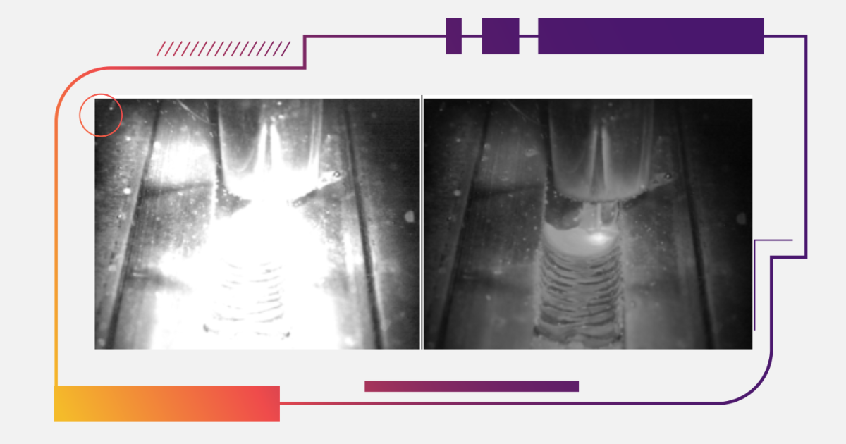
Monitoring tools make it possible to see distortion risks as they form. Weld cameras show bead size, arc position, and alignment clearly, giving teams a chance to adjust before heat buildup causes movement. Recorded images also provide feedback for improving future welds.
Detecting and Measuring Distortion
Even the best prevention plans need checking. Distortion develops gradually, and small shifts are much easier to correct than large ones. Measuring during welding shows whether the sequence is working, while post-weld inspection confirms if the final geometry meets requirements.
In-Process Monitoring
Distortion begins while the weld is still being laid down, so the sooner it’s noticed, the easier it is to correct. Simple checks with straightedges or gauges can catch movement between passes, but they only show single points. Weld cameras make the process more responsive by showing the entire bead as it forms. Small changes in bead width, arc position, or gap closure can be seen live, and overlays highlight when dimensions start to drift. With that information, operators can adjust travel speed, balance the sequence, or pause for cooling before the distortion locks in. Live monitoring is the best way to solve distortion: by catching it just as it starts to form and stopping it in its tracks.
Post-Weld Dimensional Checks
Once welding is complete, the geometry of the part needs to be confirmed before it moves on to machining or assembly. Flatness, twist, and shrinkage can be checked with simple templates on repetitive jobs, while digital tools are useful when shapes are more complex or tolerances are tight. Weld cameras support this stage by giving a clearer picture of whether the welds stayed within expected limits, so inspection isn’t limited to static measurements alone. These checks ensure that distortion has been kept under control and help decide the next step. If the part is within tolerance, it can move forward confidently, and if it isn’t, inspection shows early on that repair will be necessary.
Repairing Distorted Parts
Even with good planning, distortion can still appear. When that happens, the focus shifts to restoring geometry without introducing new problems. Repair usually falls into three categories. Mechanical straightening uses force to bend the part back. Thermal straightening uses controlled heating to pull the metal into line. Sectioning removes the distorted area and allows the joint to be welded again with a better sequence. Each method suits different situations, and the choice depends on material thickness, type of distortion, and how much correction is needed.
Mechanical Straightening
Mechanical straightening relies on presses, clamps, or jacks to push a part back into shape. It works best on thin sheet or mild steel where distortion is moderate. The key is spreading the force so that correcting one bend doesn’t create another. Work gradually and check alignment often. Mechanical methods are usually the quickest and cheapest first option, but if the part springs back or resists, other methods may be required.
Thermal Straightening
Thermal straightening uses heat lines to shrink metal in specific areas. When the heated zone cools, it contracts more than the surrounding material and pulls the part back into position. This method is suited to heavy sections where mechanical force would be impractical. Success depends on placing the heat lines carefully and keeping temperatures under control so the material isn’t weakened. Thermal correction should be applied step by step, with checks after each cycle.
Sectioning and Re-Welding
When distortion is severe or complex, cutting out the affected area and welding it again is often the most reliable fix. The process involves removing the distorted section, restoring fit-up, and planning a sequence that avoids repeating the same problem. Shorter beads, alternating sides, and balanced passes reduce the chance of the distortion returning. Although it requires more work upfront, sectioning can save time compared to repeated failed attempts at straightening.
Conclusion
Welding distortion is the visible shape that hidden forces leave behind. It comes from the same heating and cooling that makes strong joints possible, and it can be managed with the same level of intent we apply to penetration or strength. Keeping parts stable means balancing thermal input, joint layout, stiffness, and sequence so contraction forces cancel instead of accumulate. That balance is easier to achieve when we can actually see what the process is doing. Tools like Xiris vision systems give welders the visibility needed to guide the process in real time and keep geometry steady. That’s why weld cameras are so important for maintaining consistency across builds and reducing the risk of distortion. With this level of control, distortion shifts from being a costly problem to a parameter that can be planned, monitored, and steadily improved.

|