Fuel line tubing is typically manufactured on an ERW welding mill similar to traditional seam welded tubing. Once the tube has been welded, it moves down the mill for further in-line processing that may include reducing, sizing, annealing and coating processes to meet the customer’s needs.
Fuel line tubing must be perfectly round in order to create a good seal when compression fittings are applied to it. The tube surface must be free from longitudinal scratches, grooves or beads in order to prevent a leak path from developing at the interface point of the fittings.
Immediately after the fuel line tube has been welded and before any further in-line processing is done, the weld bead must be scarfed (the process whereby the weld bead is cut off with a knife). Unfortunately, the scarfing process can be the primary contributor to creating a leak path on a compression fitting because:
1. Insufficient scarfing can leave a small portion of the weld bead protruding from the surface of the tube. This may be on either one or both sides of the weld bead where scarfing tool positioning is critical.
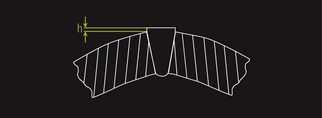
Insufficient Scarfing
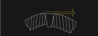
2. Excessive scarfing may look perfectly round to the human eye however a non-uniform wall thickness may be lurking below the surface. What is not always apparent and usually only observed during thorough end cut inspection is a thinned portion of the tubing wall that may compromise the integrity of the tube. The reducing process applies enough external force to the tube that the tube may buckle or collapse, causing a deep surface groove.
Excessive Scarfing
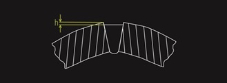
3. A mismatched setup may also be a contributor to a non-uniform wall thickness. The scarfing tool may cut the bead on the outside diameter so that it looks perfectly round to the human eye, disguising the compromised wall thickness below the surface. Sufficient mismatch conditions will most certainly cause the tube to split on end forming later in the fabrication process.
 Mismatched Defect, Post Scarfing
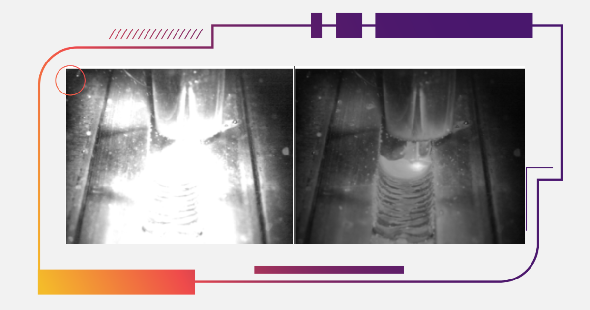
The Xiris WI2000/3000 Weld Inspection System uses laser-based imaging techniques to continually monitor the scarf zone for any variations in the scarf height, seam mismatch and possible scarf tool wear or chips that may cause a longitudinal line on the tube. By detecting and responding to these conditions proactively, a mill operator is able to reduce the chance of a leak path on the tube and avoid an unplanned stoppage to the mill due to a tube collapse during the reducing process.
For more information on how a Xiris Weld Inspection System can enhance your scarfing processes visit Xiris.com
Don't miss any of our amazing weld videos! Sign up to receive the