
The XVC-O Weld Camera system includes a computer for processing, storing, and displaying high dynamic-range images. With a computer that can perform image-processing functions on the video, operators have better control over how weld videos are displayed on a digital monitor.
Depending on their source, HDR video from Weld Cameras may have up to 16 bits of data per color channel, whereas most digital monitors support only 8 bits of color per channel. Therefore, in order to display video from the cameras, some processing must be performed to reduce the detail in the image down to 8 bits per channel. This process is typically referred to as tone mapping (although strictly that term applies only when the images are color).
For monochrome images, conventional tone mapping techniques may be as simple as displaying the top 8 bits of the input data. The problem with this technique is that it will result in a significant loss of detail in the dark areas of the image. With a bit of knowledge of the process and assistance from the operator, a much more useful tone mapping technique can be implemented.
Tone Mapping in Welding
In the case of welding, we know that the details of the welding process will be primarily in the brightest areas in the image and that the details of the work piece are likely in the darkest regions of the image. Thus, a mapping algorithm can be implemented that compresses the middle ranges of the brightness spectrum much more than the dark and bright regions. A process can be implemented to switch between mapping algorithms depending on whether a weld arc is present or not. Additionally, to fine-tune the process, the operator can define which areas of the image should retain the most detail, such as the arc vs. the background, as in the images below. (Note that the red pixels in the image with background bias indicate areas of saturation.)
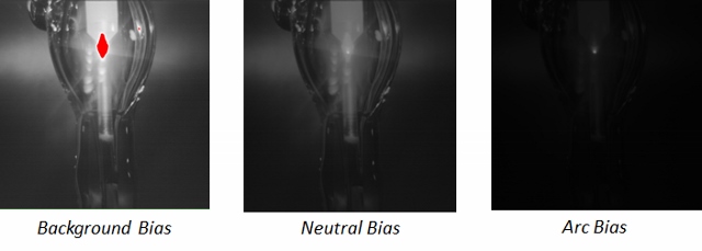.jpg?width=500&height=178&name=image_processing_biases_(640x229).jpg)
In some cases, the full dynamic range of the input image may not contain valid information. In these cases, the tone mapping algorithms can detect and react accordingly to select the appropriate range of pixels to display, and can also create dynamic mapping processes to display these pixel ranges across the full display range, a process known as dynamic equalization.
Caution must be taken when applying these techniques to some welding processes that produce bright flashes of light, because they will cause unnatural appearance of the flash appearing darker than the rest of the video stream!

In the above images, the equalized image (on the right) is based on the original, or un-equalized image on the left, with its pixel range stretched so that the pixel values exist across the full display range.
Conclusion
The best Weld Camera system in the world is of little use to a welding operator if the images are not displayed properly. Because images of a welding scene could use up to 16 bits of color per channel, but only 8 bits of color can be displayed on a typical digital monitor, the correct image processing techniques are required to properly map the acquired image into a suitable representation on an 8-bit digital monitor.
.png)
.png)
