|
Resistance spot welding is widely used in manufacturing due to its operational speed and simplicity. It creates individual welds by generating localized heat through electrical resistance, without requiring filler material. However, because it does not leave a continuous bead and lacks visible indicators of fusion, internal defects can go unnoticed during surface inspection. These flaws may only become apparent under mechanical stress, often long after production is complete. This can be prevented by identifying the types of defects that can occur during resistance spot welding, recognizing the conditions that lead to them, and applying prevention strategies such as welding monitoring systems.
Types of Resistance Spot Welding Defects
Expulsion: Molten Metal Ejection from Excessive Heat Input
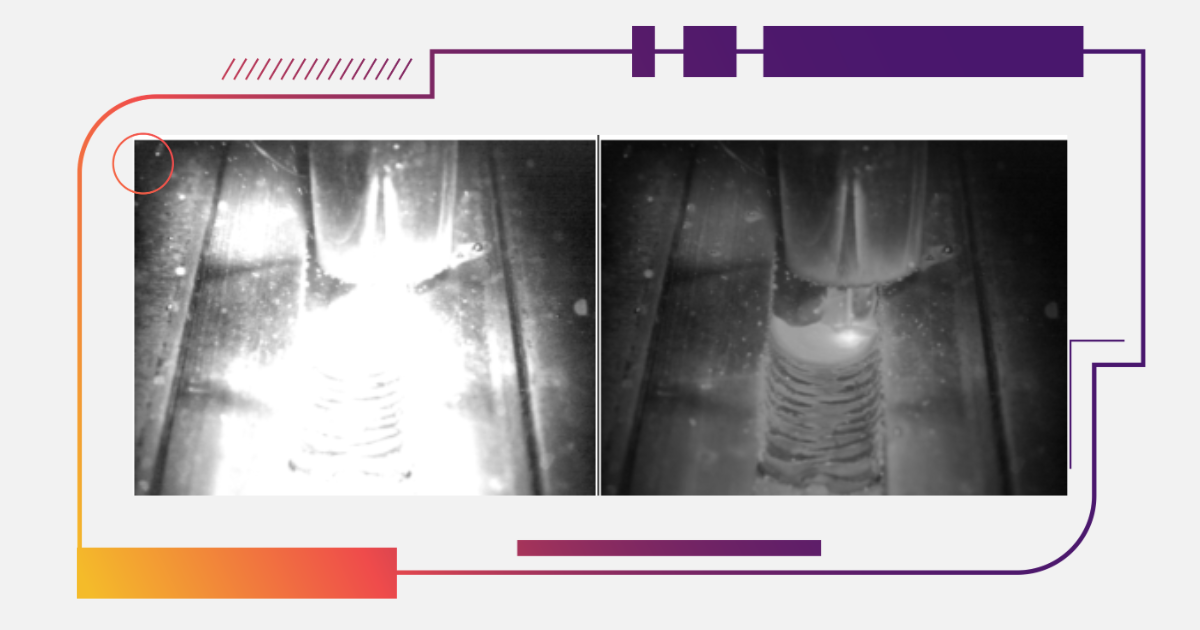
Expulsion involves the uncontrolled ejection of molten metal from the weld zone. It occurs when the heat input surpasses the containment capability of the interface. This is often caused by excessive current, insufficient electrode force, or prolonged weld time. The expelled material reduces nugget integrity, creates surface indentations, and may introduce voids around the center of the weld. These irregularities compromise mechanical performance by diminishing effective cross-sectional area and introducing stress concentrations.
Thermal imaging enables early detection of expulsion by capturing abrupt temperature increases at the weld interface. If heat concentration exceeds predefined limits, operators can adjust current or force to prevent further thermal instability.
Shrinkage Voids: Internal Cavities Formed During Uneven Solidification
Shrinkage voids originate from nonuniform cooling and solidification of the weld nugget. Rapid thermal contraction across the nugget volume creates unfilled spaces or traps gas, particularly near the core where cooling is fastest and thermal gradients are steepest. These voids decrease the joint’s structural integrity and act as points for fatigue crack initiation.
Materials with higher carbon equivalence, such as dual-phase steels, are more susceptible to this defect due to their thermal conductivity and microstructural properties. Thermal cameras provide visibility into post-weld cooling behavior. When solidification patterns deviate from known profiles, especially in asymmetric ways, the likelihood of void formation increases.
Solidification Cracks: Grain Boundary Separation Under Thermal Stress
Solidification cracks result from tensile stress acting on grain boundaries during the final phase of cooling. These cracks typically run perpendicular to the contact plane and are more frequent in materials containing elevated levels of sulfur, phosphorus, or carbon. Steep and uneven thermal gradients produce directional shrinkage that separates grain boundaries before full solidification, creating weak points within the nugget.
Such defects reduce weld cohesion and often remain hidden until mechanical testing or in-service failure occurs. Real-time thermal imaging allows visualization of solidification dynamics. Patterns of uneven contraction or directional heat loss can serve as indicators of crack risk, especially in alloys with known susceptibility.
Causes of Spot Welding Defects
Process Parameter Imbalance
Resistance spot welding depends on the precise interaction of electrode force, electrical current, and weld duration. Deviations in one parameter require proportional adjustments in the others to maintain process stability. High current without increased force raises expulsion risk, while extended weld times under marginal force can cause overheating, softening of the heat-affected zone, or internal voids.
Process instability is the primary contributor to weld defects. Preventing it requires accurate parameter calibration and continuous monitoring, particularly in automated environments where minor drifts can accumulate into systemic errors.
Material Sensitivity
Material composition and microstructure significantly influence weld quality. Steels with dual-phase structures and higher carbon equivalence tend to exhibit greater sensitivity to thermal input. Elevated carbon levels increase susceptibility to cracking and void formation. Sulfur and phosphorus reduce grain boundary cohesion, which further amplifies this risk under rapid heating and cooling conditions.
Successful welding requires matching process settings to the material’s specific thermal and mechanical characteristics. Parameters that work for mild steel are not directly transferable to advanced high-strength grades.
Cooling Dynamics
The cooling phase after welding is critical to defect formation. Rapid or uneven cooling introduces residual stresses that can promote void development, crack propagation, or distortion of the nugget geometry. These defects may remain hidden from surface inspection but significantly weaken joint performance.
Thermal imaging captures real-time data on cooling symmetry and rate. By comparing actual cooling curves to validated benchmarks, engineers can identify inconsistencies and make timely adjustments to the process.
How to Prevent Resistance Spot Welding Defects
Monitoring Weld Behavior with Welding Cameras
Welding cameras offer continuous, non-contact observation of heat behavior during the weld cycle. They allow operators to assess thermal input, distribution, and dissipation in real time, enabling immediate identification of anomalies that lead to defects.
Specific applications include:
- Detecting heat spikes that signal incipient expulsion.
- Verifying symmetrical heat distribution during nugget formation.
- Monitoring solidification to reveal irregular cooling paths or directional shrinkage.
- Storing temperature profiles for correlation with inspection results and process validation.
In high-volume production environments, welding camera systems act as a real-time feedback mechanism that enhances process control beyond what is possible with conventional parameter monitoring.
Adjusting Welding Parameters Based on Observed Behavior
Although welding cameras highlight process issues, corrective action depends on precise parameter control. Preventive adjustments may include:
- Increasing electrode force to counteract higher current levels and suppress expulsion.
- Reducing weld duration to prevent overheating in sensitive materials.
- Tuning current settings to match sheet thickness and alloy properties, ensuring proper fusion without excessive heat.
Controlling Cooling and Solidification for Structural Integrity
Solidification must proceed under controlled thermal conditions to avoid defect formation. If cooling is too rapid or uneven, the nugget may develop internal cracks or voids before solidification completes.
Effective cooling control involves:
- Balancing heat extraction between electrodes, particularly when welding dissimilar metals.
- Matching cooling curves to the material’s metallurgical requirements.
- Using thermal data to refine hold times or adjust electrode geometry for optimal solidification.
Linking observed cooling patterns with defect trends enables development of more resilient weld schedules tailored to specific joint configurations and materials.
Conclusion: Minimizing Defects Through Process Control and Visual Monitoring
Resistance spot welding yields consistent joints when process parameters are properly balanced and aligned with material properties. However, defects such as expulsion, shrinkage voids, and solidification cracks often originate from thermal and mechanical imbalances that are not visible through surface inspection. Welding cameras provide real-time visual access to the weld zone, enabling the early detection of abnormal heat behavior during both fusion and cooling phases. When integrated into production workflows, these systems enhance control, validate parameter effectiveness, and support the development of defect-resistant weld schedules. Their use shifts quality assurance from post-process inspection to in-process stabilization, reducing reliance on destructive testing while improving joint reliability in demanding manufacturing environments.

|