|
In the oil and gas industry, pipelines are typically made from sections of carbon steel pipe that are 40 feet / 12.12m long. Such pipelines are either buried underground if they traverse land or are laid on the sea bottom if they travel offshore. To manufacture an offshore pipeline, sections of pipe are welded together on land (at a port) in a “string” of up to 500+ m or so.
The resulting string is then wound on a giant bobbin loaded on a ship (or laying barge) where it will be eventually despooled for laying the pipe on the sea bottom. As part of the installation process, the ship welds one end of the string to the existing pipe segment that has already been laid on the sea bottom and is partially underwater. Once the weld is complete, the balance of the string is spooled out to the sea bottom. The process continues until the pipe is fully in place.
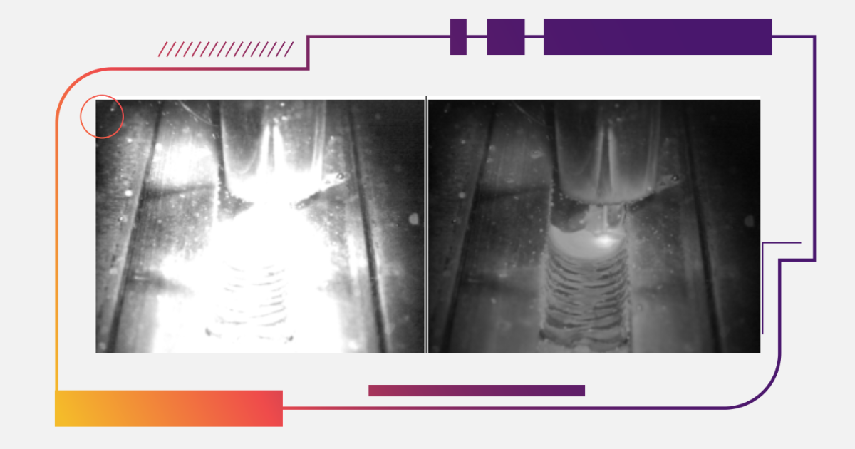
.png?width=600&height=467&name=Weld%20Bead%20Inspection%20(zoom%20inside).png) |
Why Root Pass Weld Quality Matters
To weld two sections of pipe, the ends are brought together, then centralized and tack welded to hold them in place. The weld root pass is then performed in a centrifugal method from outside the pipe where the weld torch moves all around the circumference of the pipe.
The root pass is the most critical weld, not only because it is the foundation for the rest of the weld bead but also because the height of the back side of the root pass that faces into the pipe must be carefully controlled (the “protrusion height”) to ensure it does not affect product flow inside the pipeline once in use. So, the root pass height inside the pipe needs to be very carefully monitored to determine if it is protruding too far into the pipe cross section.
Using Camera Systems for Internal Pipe Weld Inspection
To solve this, giant welding service providers who work in the pipeline industry provide welding services using camera systems to look at the welds. Such camera systems are mounted on travelling crawler devices, taking pictures of the back side of the root weld to determine if some machining or repairs of the root pass weld are necessary. Typically, the crawler/camera combination could be driven up to 2 km into the pipe, then slowly pulled out, stopping every 40’/12.12m to check the backside of each circumferential weld, looking for issues such as:

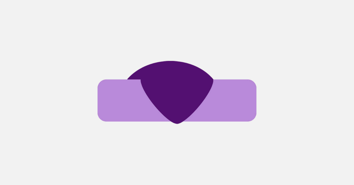
Fig. 2 Raised Bead |

Fig 3. Sunken Bead |
Fig. 2/3. Bead Height - the height of the center of the bead after welding, measured relative to the height of the parent material. Characterized as a raised bead (Fig. 2), or sunken bead (Fig. 3)

Fig. 4. Mismatch |
- Uneven Joining of the two Segments of the Parent Material. Also often known as “Mismatch” or “High-Low”

Fig 5. Weld Undercut |
- Height of the Lowest Side of the Weld Bead Relative to the Parent Material. Formed When the Welding Power Source is too far Off Center of the Weld Seam

Fig. 6. Weld Color |
|
Average of the Actual Color of Weld Bead and Surrounding Material Across a Region of Interest (ROI)
|

Fig. 7. Holes or Porosity Defects |
– Contamination or Air Pockets Captured in the Weld Bead
And other defects that are of interest. The service provider usually wants to measure the weld bead geometry and take color photos of the weld looking straight down to feed the operator good quality images of the weld to verify that it is defect free.
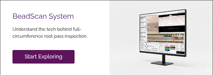
How the BeadScan system captures 2D weld bead geometry using high-resolution imaging and precise scanning.
To serve this application, Xiris has built a new camera solution for the pipeline market, known as BeadScan, to address these problems with some innovative software features. Having supplied the global welded tube and pipe industry with a highly precise weld bead geometry system for many years, Xiris has migrated that technology to the measurement of pipe welds for the pipeline industry. The BeadScan system accurately scans, records, and optionally measures, the surface geometry of the weld bead and creates a 2D visual image of the welded bead on the back side of the root pass on pipelines.
Full Circumference Imaging for Root Pass Quality Control
Such weld inspection and imaging capability allows the BeadScan system to ensure the integrity of the root pass weld in applications that are difficult to see manually on a welded pipe. The surface geometry of the back side of the weld bead can be analyzed to determine if the first pass was properly welded with multiple optional measurements. In addition, a very high resolution, on-axis 2D image can be created by making a complete visual recording of 360 degrees of the weld bead as an operator aid to further diagnose defects in the weld.
Sample Images and Data

Fig. 8: User Interface showing a Good Weld Bead with some Narrowing of its Width. |
Conclusion: Safer Pipelines with Visual Weld Bead Inspection
To obtain precise measurements of the protrusion height of the weld bead into the pipeline and confirmation that the root pass weld bead is of sufficient quality, a camera system such as the Xiris BeadScan system can be added to a mechanical crawler device that can carry the camera system through a pipeline and stop at weld joints along the way to perform a traceability and quality control analysis, perform visual inspection and laser measurements of the weld bead, with the ultimate goal of making pipelines safer and more economical.
|