|
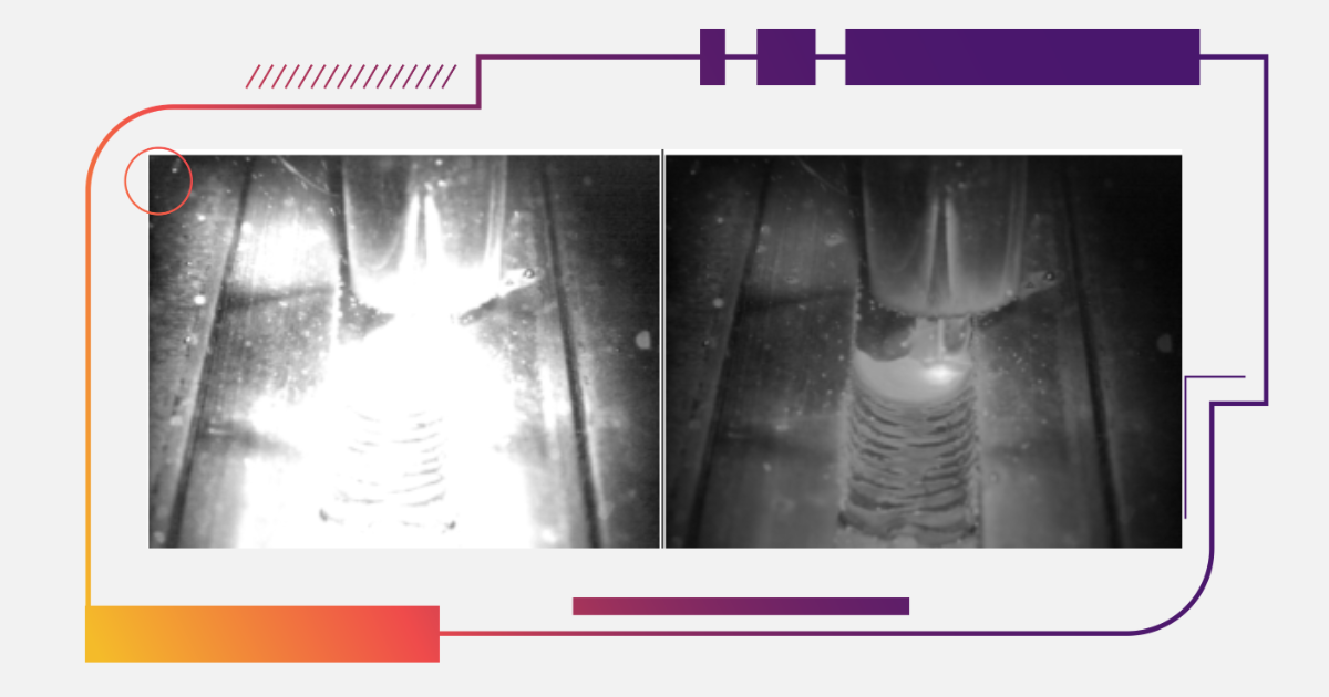
In welding processes where precision and structural integrity are critical, surface discontinuities such as overlap present persistent challenges. This defect not only undermines joint strength but also increases the risk of failure under cyclic loading or thermal stress. As industrial applications demand tighter tolerances and improved weld quality, accurate detection and prevention of overlap become essential. Thermal cameras, used for monitoring arc behavior and melt pool dynamics, are increasingly integrated into welding setups to identify heat distribution anomalies that may precede overlap. By combining visual inspection with thermal data, operators gain an enhanced view of heat flow, melt pool stability, and potential discontinuities across complex weld geometries.
What Is Overlap in Welding?
Overlap is a surface discontinuity that occurs when molten filler metal flows beyond the intended weld toe without bonding to the base material. This defect is characterized by excess weld metal solidifying along the base surface without metallurgical fusion. Unlike undercutting, which involves material removal from the base metal, overlap results from surplus deposition without proper wetting.
This condition is typically observed in fillet welds, particularly where horizontal or overhead positions complicate gravitational control of the melt pool. Overlap is also prevalent in lap joints when poor fit-up or inconsistent heat input compromises fusion at the edges.
What Causes Overlap in Welding?
- Travel Speed and Deposition Rate
When the welding torch moves too slowly or the filler deposition rate is excessive, molten metal accumulates faster than it can be properly fused to the base. This imbalance results in overflow, where liquid metal spills past the joint boundary.
- Improper Torch or Electrode Position
A steep or inconsistent torch angle redirects the arc force away from the fusion line. Without consistent energy delivery to the joint edge, filler metal pools and solidifies without metallurgical bonding, forming surface overflow.
- Inadequate Heat Input
Insufficient arc energy leads to incomplete fusion at the weld boundary. Even when deposition is correctly aligned, a cold weld front can prevent full wetting, causing deposited metal to cling rather than fuse.
- Joint Fit-Up and Surface Condition
Poorly prepared joints, contaminated surfaces, or irregular edge geometries interfere with uniform heat transfer and filler distribution. In such cases, arc movement may favor one side, promoting asymmetrical deposition and overlap.
Where Does Overlap Typically Occur?
Overlap is most frequently found in the following scenarios:
- Fillet welds: Especially at the toe, where weld buildup is prone to escape lateral boundaries.
- Lap joints: Where one plate overlays another, inconsistent edge fusion can result in surface flooding.
- Overhead or horizontal positions: Gravity causes the molten pool to drift and accumulate where control is reduced.
How to Detect Overlap in Welding
Visual Identification
Overlap can often be identified by its rolled-edge appearance and absence of a gradual transition into the base material. Unlike a fused toe, the excess metal forms a ledge with minimal blending.
Overlap Inspection Tools
Profile gauges, undercut comparators, and magnification can assist in confirming surface geometry. Thermal cameras, while not traditionally employed for surface profile measurement, can detect anomalies in cooling patterns. Areas with excess mass and poor fusion often exhibit localized temperature gradients distinct from the rest of the bead.
Nondestructive Testing Methods
Dye penetrant testing reveals open-surface discontinuities by capillary action. Where surface accessibility is limited or visual confirmation is inconclusive, 3D profilometry and ultrasonic inspection can provide quantitative assessment. Infrared thermography also assists in post-process evaluation, highlighting thermal inconsistencies at weld edges, which may correlate with non-fused deposits.
How to Prevent Overlap in Welding
Controlling travel speed in relation to the wire feed rate is essential for maintaining melt pool stability. Excess filler or reduced movement increases the risk of overflow beyond joint boundaries.
Torch orientation also influences heat distribution. A consistent angle and steady arc length direct energy into the fusion zone, promoting uniform wetting. Xiris thermal cameras aid in refining these parameters, offering real-time visibility into temperature gradients that may indicate early signs of overlap.
Surface preparation further affects weld behavior. Cleaned, beveled edges with accurate fit-up ensure consistent arc performance and filler distribution.
Finally, adjustment of voltage, current, and feed rates must correspond to the selected process—whether GMAW, GTAW, or FCAW. Thermal imaging systems enable in-process feedback by visualizing arc symmetry and melt pool behavior, allowing operators or automation controllers to adjust travel speed and energy input before excess deposition occurs.
How to Fix Overlap Welding Defects
Grinding and Rewelding
Overlap must be removed entirely. Grinding or machining the excess metal allows re-exposure of the base surface for proper fusion. Rewelding is performed with adjusted parameters to correct the original imbalance.
Post-Repair Inspection
Following removal and reapplication, the weld should be reassessed using visual and nondestructive techniques. Thermal imaging can confirm uniform cooling behavior, indicating a continuous and bonded mass throughout the weld zone.
Welding Overlap vs. Other Welding Defects
Overlap differs from other discontinuities primarily in geometry and mechanism:
- Undercut: Material loss at the toe, forming a groove that weakens structural integrity.
- Lack of fusion: Internal discontinuity, where adjacent weld passes or joint faces do not bond.
Overlap may result from similar root causes but manifests as surface accumulation rather than internal or edge voids.
Summary
Overlap is a welding defect caused by excess molten metal failing to fuse to the base material. It typically arises from improper travel speed, torch positioning, or inadequate heat input, and is frequently observed in fillet and lap welds. Detection methods include visual assessment, dimensional gauges, and increasingly, thermal imaging tools capable of revealing uneven heat patterns. Prevention is rooted in precise parameter control and joint preparation, with thermal feedback offering a valuable enhancement for real-time quality assurance.
|