
Recent advancements in machine vision technology have made a new type of inspection able to see defects related to the forming and welding area of a tube or pipe. The result is improved quality assurance and process control on the production line. The new type of inspection device is a laser-based triangulation system that measures the outside contour of a tube or pipe in the vicinity of its weld.
Typically NDT systems are placed at the end of a production as a final check. However, the laser inspection system can be placed directly after the weld box, This system can let operators know what is changing in their welding process, allowing them to perform corrective action before significant scrap occurs. This capacity is especially helpful for one of the most common defects found across all types of Tube manufacturing: Tube Mismatch.
The Mismatch Defect
The Mismatch defect is caused by uneven joining of two edges of the tube material strip before welding. Mismatch is a vital parameter to monitor for all tube and pipe fabricators, regardless of which side is higher. This is because many mills employ a grinder or scarfing process to remove any excess bead that is out of round. However, if mismatch occurs prior to welding, once the tube bead has been removed, part of the wall on the high side of the mismatch may get removed as well, causing significant thinning of the tube wall or leave a step on the lower side after grinding the weld area.
Sometimes the actual welded tube wall thickness in the area of the bead becomes smaller than the original tube wall thickness. This is a result of processing steps other than material removal, such as corrugation or bending of the tube, which can create additional potential failures if a Mismatch defect is also present.
Mismatch is calculated as the absolute value of the radial difference between the two reference points where the weld bead meets the parent material. The mismatch calculation uses the current roll angle to compensate for the bead roll, as such:
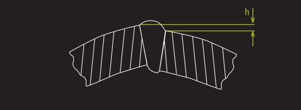
The Mismatch Defect, where “h” = the height of the defect.
How the System Measures the Mismatch Defect
Xiris Automation Inc. has developed a non-destructive inspection system called the WI2000p Weld Inspection System. The WI2000p includes a laser line and a camera whose optical axis is offset to the axis of the laser line by an “offset angle”. The WI2000p creates a visible cross-section of the tube by projecting the laser line on to the tube and capturing an image of the line using the camera. The resulting image shows a profile of the tube surface as if it were cut in cross section. If a tube is ideally round, the laser image will represent a section of an ellipse and any anomaly such as a Mismatch can be mathematically detected.
The WI2000p bases all of its measurements on the differences between the actual laser profile line seen by the camera, and the ideal mathematical profile based on the tube parameters. By knowing the position of the actual laser profile, the ideal profile, and the size of the pixels in the image, the WI2000p can detect Mismatch profile defects that often escape detection by other quality tools such as Eddy Current testing, or Ultrasonic Testing techniques
Conclusion
A new technique for detecting Mismatch on welded Tube and Pipe has been developed by Xiris and is known as the WI2000p weld inspection system. The WI2000p system is a laser based system that is capable of detecting Mismatch defects immediately after welding to alert the operator of a defect in time to minimize rejects. The result is improved quality, fewer field defects and a more reliable method for the operator to optimize the welding process.

.png)
