|
Every welder comes across an undercut sooner or later. It’s one of those defects that sparks debate in the shop: is it worth fixing, or can the joint stay as it is? The answer isn’t always obvious, because undercut lives on the borderline between cosmetic blemish and structural concern.
In this article, we’ll talk about what the undercut defect actually is, how to recognize it, the conditions that cause it and the possible consequences it may have. Deciding the next step comes down to how the groove was formed, where it’s located, and what the part will be asked to endure. Understanding those factors makes it easier to decide whether a weld should be redone, blended smooth, or simply left in place.
What Is Weld Undercut and Why It Matters
Undercut is a groove that forms along the toe of a weld where base metal melted and then failed to refill as the pool solidified. It often appears as a narrow channel cut into the parent plate right at the junction between bead and base metal. You’ll spot it on fillet toes, butt joints near starts and stops, and on edges that run hot with high travel speeds. On clean material under good light the surface looks scooped out, sometimes with a bright edge. Although it can look minor, that little groove changes both the local thickness and the way stress flows through the joint.
What Weld Undercut Looks Like
When undercut is present the toe line stops being a smooth curve and becomes a channel that you can trace with a fingernail or gauge tip. The channel can be intermittent, appearing as short segments, or it can run continuously for long distances. Width is usually small, but the key is how deep and sharp it is. On carbon steels, a fresh undercut often shows a bright edge after cleanup, while on aluminum it can appear as a fine trough that catches light. You’ll notice it more on flat and horizontal positions where high travel speeds and a lively pool leave the edge behind. Starts and stops tend to exaggerate it because the pool transitions quickly and metal doesn’t always refill the toe. If spatter is present, it can hide the groove until you remove it.
How to Detect Undercut in Welds
Detection begins with clean surfaces and controlled light. Wipe the joint, remove spatter and use angled illumination so the groove casts a small shadow. A low profile mirror helps for cramped geometry. A simple undercut gauge or a depth scale on a fillet gauge lets you feel and measure the channel, not just see it. Run the tip along the toe and note changes in depth and continuity. Take close images with consistent scale so later decisions are traceable. Many teams use weld cameras during production to reveal toe wetting and edge behavior while the pool is still fluid. Cameras with HDR reduce arc glare and capture detail in both the bright pool and the darker base. NIR filtering reduces radiation glare so the toe line is clearer, which is useful when the arc washes out visible light.
|
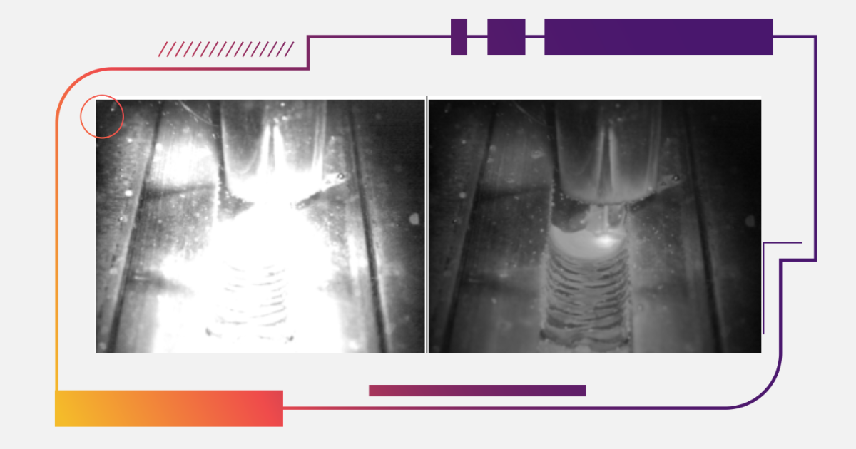
This footage shows the formation of an undercut defect in gas metal arc welding (GMAW) of a fillet weld.
Source: Welding Defects Guide
|
Why Weld Undercut Happens
Undercut is a predictable outcome of how molten metal moves and freezes. If travel speed is high relative to heat input, the melt pool thins and the toe stops being fed at the exact moment it needs reinforcement, so metal recedes and a groove remains. A long arc and higher voltage flatten the pool and push fluid away from the edge, making wetting at the toe less reliable. Torch or electrode angles that pull the arc force toward the plate face can wash material off the edge, especially on thin sections and sharp plate edges. Wire size and current density interact too. A small wire at high current gives a hot, forceful stream that can erode the toe faster than filler arrives. Joint geometry matters because sharp edges and poor fit up act like tiny dams that disturb flow at the boundary. Slag systems and shielding also influence surface tension, which changes how easily the pool climbs the toe.
Why Undercut Defects Threaten Weld Integrity
The toe of a weld is where stress changes direction. Instead of flowing through uniform plate, load bends around a geometric transition. A smooth curve spreads stress gently. A sharp groove compresses stress into a tight region that becomes sensitive to micro flaws and surface damage. That’s why an undercut with a small radius can behave like a notch. Under cyclic loading the stress reversal pumps the notch and promotes micro crack growth. In corrosive environments the groove can collect residue and moisture, creating a local chemistry that attacks the edge faster than surrounding metal. Even when loads are mostly static, a long, deep channel reduces the effective cross section and raises the local stress.
How to Evaluate If an Undercut Weld Must Be Redone
When welders encounter undercut, the toughest part isn’t spotting it, it’s deciding what to do next. Some grooves are small and isolated, others are deeper and run for several inches, and the impact of each case can be very different. The decision about whether to redo a weld, blend the groove out, or simply leave it in place depends on more than just appearance. It’s tied to where the defect sits, how sharp or continuous it is, what material is involved, and how the part will behave once it’s in service.
Impact of Undercut Location on Weld Performance
An identical groove behaves differently on a decorative bracket than on a bracket that carries alternating loads near a bend. Areas where force changes direction, such as toes near corners or thickness transitions, are less tolerant of sharp surface relief. Attachments near discontinuities, stiffener ends and start stop zones concentrate stress naturally, so any notch adds to that concentration. Think about how the part is supported and where the peak stress sits under real use. If the toe with undercut aligns with the path of highest tensile stress or sits near a feature that already gathers strain, the margin shrinks. By contrast, undercut on free edges, or in regions where stress is mainly compressive, tends to be less influential. This isn’t guesswork. Sketch the load path, mark the groove locations and ask how a small reduction in section and radius would change the local picture. If the answer points to rising peak stress, the case for rework strengthens. If the load path avoids that region, a blend can be entirely rational.
Assessing Undercut Geometry and Depth in Welds
Geometry turns a visible groove into an engineering variable. Depth reduces local thickness, which raises stress. Radius sets how sharply stress concentrates at the toe. Length and continuity control how much of the joint is affected at once. A short, shallow mark with a smooth transition is a different animal than a long, constant depth channel with a knife like edge. Use a profile or undercut gauge to record representative depths along the run, not just a single spot. Note whether the groove is isolated or repeats with a rhythm that hints at a process issue. Photograph the toe at consistent scale and angle so radius can be compared after blending or repair. If you decide to leave the joint as is, this record becomes the baseline for later checks. If you proceed with blending or overlay, it lets you confirm an improved profile. In either case, measurements teach patterns: teams begin to recognize which combinations of depth, radius and length actually correlate with trouble in their products.
Material and Service Factors Affecting Undercut Risk
Materials carry their own sensitivities. High strength steels develop higher stress at a given load, so sharp surface relief in those alloys acts more aggressively than in mild steel under the same geometry. Aluminum alloys can be notch sensitive, and the oxide behavior of the surface makes toe blending and cleanliness more important after any rework. Duplex and austenitic stainless steels bring corrosion factors that interact with surface grooves in different ways, especially if chlorides or heat tint are part of the environment. Service conditions add another layer. Cyclic loads, even at modest amplitude, grow small flaws over time. Vibratory service in machinery can turn a minor notch into a long term initiator. Thermal cycling moves the joint through expansion and contraction, waking up regions near geometry changes. Fluids and weather add chemistry into the mix. None of this means every undercut is dangerous. It means the same groove can be harmless on one material in a calm environment and risky on another exposed to cycling and corrosion.
Using Inspection Evidence to Judge Undercut Severity
Inspection evidence makes the decision about undercut more objective. Begin by taking clear images under angled light so the groove at the weld toe is visible. Follow this with depth readings at several points along the weld to see how deep the undercut runs and whether it’s continuous or isolated. A repeating pattern every few inches often points to issues with travel speed or puddle stability.
If cameras are available, review short clips of the weld as it was made. Pay attention to how the pool wets at the toe, whether the arc stayed stable, and how the bead edge behaved when angles changed. HDR imaging reduces glare so both the pool and base metal remain visible, and NIR filtering minimizes arc brightness, making the toe line easier to evaluate.
Combine these observations with notes on the material and the service conditions. That way, the choice to blend, re-weld, or leave the joint as it is comes from measurable evidence rather than guesswork.
How to Inspect and Measure Undercut in Welds
Inspection gives you the information needed to judge whether an undercut weld should be repaired. The aim here isn’t to make the process complicated but to make it consistent. Clean surfaces, good lighting, and a few simple tools are enough to reveal whether a groove is shallow and isolated or sharp and continuous. By combining visual checks, straightforward measurements, and clear documentation, you turn what could be a subjective call into a repeatable workflow.
Visual Inspection Techniques for Undercut Welds
Remove slag and spatter so the toe line is visible. Use angled light to cast shadows that reveal grooves, and mirrors for access in tight spots. Watch for breaks in the toe line where the channel interrupts the curve. Note whether the groove is continuous or appears only at starts, stops, or position changes. In automated cells, weld cameras can make this easier by showing the toe as the bead forms, with HDR and NIR options reducing glare and clarifying the edge.
Measuring the Size and Profile of Weld Undercuts
Use an undercut gauge to translate what you see into numbers. Record depth at several locations and note taper or continuity. Macro photos with a scale provide evidence of width and radius, and flexible profile gauges can capture a segment for later comparison. Some shops use laser scanning in automated cells, but a gauge and photos cover most needs. What matters is describing the groove in terms of depth, length, and sharpness so later decisions rest on measurable data.
Documenting Undercut Weld Conditions for Decisions
Tie inspection to action by recording what you find. Store labeled images, depth readings, and notes on location and surface condition. Add clips from weld cameras if available. Keep everything organized so later checks are quick and comparable. Good documentation makes it easier to decide whether blending or repair is justified, and over time it shows patterns that help refine thresholds for rework in future jobs.
How to Repair Undercut Welds Effectively
The choice is usually between blending and rebuilding. Blending removes the groove and leaves a smooth transition without thinning the edge too far. Rebuilding adds metal and re profiles the toe where blending alone won’t restore a good shape. Whichever path you choose, treat repair as a controlled mini process with defined steps and a quick check at the end.
Blending Out Shallow Weld Undercuts
Blending is the right choice when the groove is shallow and localized. Mark and clean the area so you’re working on bare metal. Use a fine abrasive wheel or flap disc with light pressure, following the toe line to keep the original geometry. The goal is to remove the sharp edge and leave a smooth radius that carries stress without concentrating it.
Check progress often with angled light and a gauge to avoid thinning the edge too far. If the groove fades and the transition looks uniform, finish with a light polish to remove grinding marks. Record the result with a quick photo and a depth reading. A successful blend leaves a continuous toe line, smooth profile, and no measurable loss of thickness.
Refilling and Re Profiling Severe Undercut Welds
Deeper or longer grooves need more than blending. In those cases, refill the channel and reshape the toe. Start by feathering the edges so new metal ties in cleanly. Adjust parameters for good toe wetting, then add a small overlay pass that rebuilds the channel instead of enlarging the bead. Keep the arc short to concentrate heat, and feed filler steadily to avoid hollows.
Once the pass cools, blend the toe to restore a smooth transition. Inspect the area with angled light and check depth and continuity. Take a macro photo to document the result. If the surface still shows a ripple, a second light pass can finish the job. The repaired toe should look natural, with a smooth curve and no visible groove, and measurements should confirm that thickness and shape are restored.
Verifying Weld Quality After Undercut Repair
Verification confirms the repair added value. Clean the area and repeat the same inspection and measurement steps used earlier. Under angled light the toe should appear as a continuous smooth line without shadows from a groove. Depth readings should show the channel removed or reduced to a harmless surface trace.
If you refilled, look for even tie-in on both sides and consistent surface texture. Take an image with a scale and store it next to the original photo for comparison. Add a short note on parameters used and any adjustments made to prevent recurrence. If weld cameras are available, capture a final clip to show toe behavior under the new settings.
How to Prevent Undercut Defects in Welds
The best way to deal with undercut is to prevent it. When parameters stay in their ideal range and the joint is prepared well, the weld pool flows smoothly into the toe instead of cutting a channel. Modern tools like weld cameras and monitoring systems make it easier to catch problems early and adjust before defects form.
Set welding parameters carefully
Keep voltage, current, travel speed, and arc length inside stable ranges. Watch heat input: too much with high speed makes the pool drain off the edge, too little starves the toe. In pulsed GMAW, tune peak and background to support toe wetting.
Control torch movement
Maintain steady contact tip to work distance, use modest weave amplitude, and pause lightly at toes without burning the edge. Small angle changes have big effects on how the pool fills the toe.
Prepare joints properly
Break sharp edges with a light chamfer, align bevels, and keep gaps consistent. Clean surfaces to avoid oxides or contamination that change surface tension. Consistent fit-up helps prevent one edge from melting away first.
Use weld cameras for visibility
Break HDR and NIR-equipped cameras reduce glare and show the toe line clearly as the weld forms. Position them to view pool wetting and tie camera output to alarms or training clips to catch problems quickly.
Apply process monitoring systems
Log voltage, current, wire feed, and speed. Dashboards or alerts highlight when values drift, allowing fast correction. Over time, this data shows patterns and prevents recurring undercut issues.
Conclusion: Making Smart Decisions About Undercut Welds
Undercut is common enough that it will keep appearing in shops and field work, but it doesn’t have to be a constant source of argument. The key is building confidence about the decision: knowing when a weld truly benefits from rework and when it can be left as-is. That confidence comes from careful observation, a clear process for evaluation, and experience supported by good documentation.
As welding technology moves forward, prevention tools such as vision systems and process monitoring make it easier to keep undercut under control. Still, the judgment about whether to redo a weld remains in the hands of the people interpreting the evidence. By giving every weld a closer look, teams improve reliability without wasting effort, and the welds that do get repaired are the ones that genuinely need it.
Frequently Asked Questions
|
|
Follow Xiris on social media for regular updates and welding videos!
![]()
![]()
![]()
![]()
Sources:
1https://garage.eastwood.com/eastwood-chatter/listen-to-your-mig/
2https://www.millerwelds.com/resources/article-library/mig-welding-the-basics-for-mild-steel
3https://forum.millerwelds.com/forum/welding-discussions/4179-mig-welding-sound
4https://www.theshedmag.co.nz/home/2018/7/8/tackling-stainless-a-guide-to-stainless-steel-welding